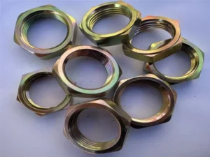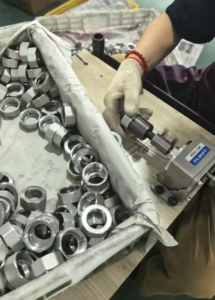
“Before we dive into the specific dimensions, tolerances, and features called out on this print, let’s establish the most critical baseline: this is an Imperial (Inch) engineering drawing for high-precision carbon steel parts, not a Metric (mm) one..
In precision CNC machining and technical DFM reviews, many machinists and engineers simply reach for a calculator to multiply nominal values by 25.4. However, working with an inch-based drawing involves far more than basic math conversion. The number of decimal places dictates the manufacturing tolerance, zero-value formatting completely changes how numbers are read, and thread pitches are defined by tooth counts rather than linear distance.
To accurately interpret the dimensions on this print, we first need to understand how Imperial values translate to Metric shop-floor reality.”
How Inch Corresponds to Millimeter (Metric)
1. Baseline Conversion & Scale Reference
-
1.000″ (1 Inch) = 25.400 mm
-
.100″ (100 thou) = 2.540 mm
-
.010″ (10 thou) = 0.254 mm (approx. 0.25 mm / rough turning band)
-
.001″ (1 thou / 1 mil) = 0.0254 mm (standard machining unit, ~2.5)
-
.0001″ (One ten-thousandth) = 0.00254 mm (approx. 2.5 μm / precision grinding & bearing journals)
2.Fraction vs. Decimal vs. Metric Equivalent
| Fraction Callout | Decimal Inch | Metric Equivalent (mm) | Common Shop-Floor Usage |
| 1/16″ | .0625" |
1.588 mm |
Wall thickness, small pin holes |
| 1/8″ | .125" |
3.175 mm |
Bleed orifices, cross-drill holes |
| 1/4″ | .250" |
6.350 mm |
Fluid passage bores, small thread roots |
| 3/8″ | .375" |
9.525 mm |
Fluid fittings, medium ports |
| 1/2″ | .500" |
12.700 mm |
Baseline 1/2″ thread major diameter |
| 5/8″ | .625" |
15.875 mm |
Hex flats, heavy shoulders |
| 3/4″ | .750" |
19.050 mm |
Wrench flat trap: standard 19 mm stock is 0.05 mm undersized |
| 1″ | 1.000" |
25.400 mm |
Nominal bar stock baseline |
3. ASME Y14.5 Decimal Rules vs. Metric Reading Habits
-
Leading Zeros (The Missing Zero):
-
Metric practice: Always write the leading zero before the decimal point (e.g.,
0.5 mm,0.02 mm). -
Imperial practice (ASME Y14.5): Values below one inch never include a leading zero (written as
.500",.020",.002"). Always check closely for the preceding decimal point to avoid reading.050"as50.
-
-
Trailing Zeros = Tolerance Binding:
-
Metric practice: Writing
12or12.00generally carries the same default tolerance per ISO 2768-m. -
Imperial practice: Trailing zeros are a direct contractual tolerance specification governed by the title block:
-
.X (e.g.,
1.5") -> Default tolerance ±.030″ (approx. ±0.76 mm) -
.XX (e.g.,
1.50") -> Default tolerance ±.010″ (approx. ±0.25 mm) -
.XXX (e.g.,
1.500") -> Default tolerance ±.005″ (approx. ±0.127 mm) -
.XXXX (e.g.,
1.5000") -> Default tolerance ±.0005″ (approx. ±0.0127 mm)
-
-
4. Thread Definition: TPI vs. Pitch
-
Metric Threads (M): Pitch is the linear travel per revolution in mm (e.g., M10 x 1.5 -> Pitch = 1.5 mm).
-
Imperial Threads (UN / NPT): Stated as TPI (Threads Per Inch).
-
CNC Program Lead (F) Formula:
-
Feed / Lead (F) = 25.4 / TPI
-
Example: A
.500-20 UNFthread has 20 threads per inch. -
CNC Lead (F) = 25.4 / 20 = 1.270 mm per revolution
-
Precision Carbon Steel Parts: Blueprint Breakdown
Below is an inch-based blueprint for a carbon steel component. Let’s dive into the detailed drawing analysis
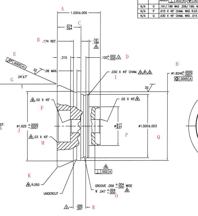
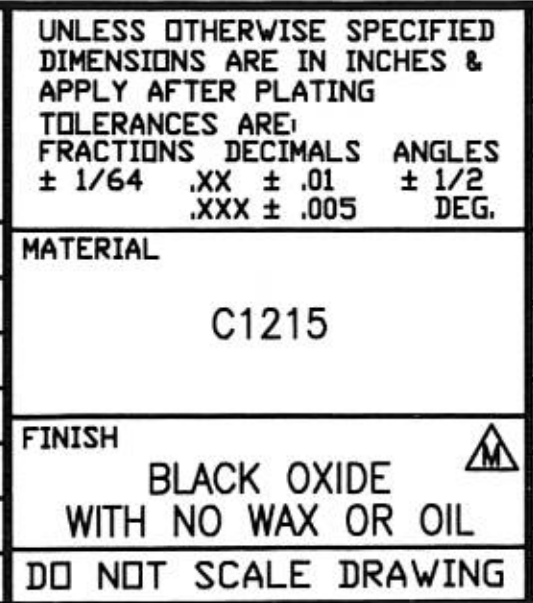
Material: AISI C1215 Free-Cutting Steel
C1215 is a rephosphorized and resulfurized low-carbon steel optimized for high-speed automated CNC turning.
-
China Equivalent: GB/T 8731 Y15
-
Other Standards: EN 1.0715 (11SMn30) | JIS SUM23
Chemical Composition (C1215 vs. Y15)
| Element | ASTM A108 (C1215) | GB/T 8731 (Y15) | Function in Machining |
| Carbon (C) | ≤ 0.09% | 0.10% – 0.18% | Keeps the matrix soft to minimize tool wear |
| Manganese (Mn) | 0.75% – 1.05% | 0.80% – 1.20% | Combines with sulfur to form MnS inclusions |
| Phosphorus (P) | 0.04% – 0.09% | 0.05% – 0.10% | Increases brittleness for clean chip breaking |
| Sulfur (S) | 0.26% – 0.35% | 0.23% – 0.33% | Acts as internal lubricant; enables 130%+ machinability |
| Silicon (Si) | ≤ 0.10% | ≤ 0.15% | Kept low to prevent abrasive tool wear |
(Note: C1215 / Y15 is strictly non-weldable due to high sulfur hot-cracking risk.)
Surface Finish: Black Oxide with No Wax or Oil (Dry Black Oxide)
The drawing callout requires an unsealed chemical conversion coating (
Fe3O4).-
Zero Dimensional Shift: The oxide layer is only 0.5 – 1.5 μm thick. Precision external threads (Class 2A/6g) and tight turned diameters require no pre-plating offsets.
-
Why No Oil/Wax: Essential for secondary thread-locking adhesive bonding (e.g., Loctite) or cleanroom/fluid assemblies where hydrocarbons cause contamination.
-
Corrosion Alert & Packaging: Without protective oil, bare C1215 rusts rapidly. Finished parts must undergo thorough hot-water rinsing to eliminate trapped caustic salts, followed by forced-air drying and airtight packaging inside sealed poly bags with VCI paper and desiccants.
Precision carbon steel parts: Feature-by-Feature Blueprint Analysis Table
| Feature ID | Drawing Callout (Inch) | Metric Conversion (mm) | Tolerance Type & Band | Shop-Floor Function & Machining Process |
| Datum A | Ø.3125 (+.0003 / -.0001)” | Ø7.9375 (+0.0076 / -0.0025) mm | TIGHT: +0.0076 / -0.0025 mm (Total 10.1 μm) | Primary Functional Datum: Central through-bore. Serves as reference axis for concentricity and angularity. Requires high-precision reaming or micro-boring. |
| A | 1.020 ± .005" |
25.908 ± 0.127 mm | Title Block (.XXX): ±0.127 mm | Overall Axial Length: Total thickness of the gear hub turned during parting-off/facing operation. |
| B | .174 REF |
4.420 mm REF | Reference Only (No inspection) | Reference Dimension: Informational layout; excluded from standard CMM/caliper QA pass-fail inspection. |
| C | .574 ~ .594" |
14.580 ~ 15.088 mm | Bilateral: Total 0.020″ (0.508 mm) | Shoulder Axial Length: Transition step locating adjacent gear/clutch interface. |
| D | 0.120 (+.002 / -.000)" |
3.048 (+0.051 / -0.000) mm | Unilateral: +0.051 mm | Shoulder Thickness: Positive-only stock allowance for mating thrust washer positioning. |
| E | `∠ .0005 | A&24° ± 7’` |
0.0127 mm runout profile; Ra 32 microinch (~0.8 μm) | GD&T Angularity Control: Max 0.0005″ deviation relative to Datum A. Maximum burr height 0.08″ (2.03 mm MAX). Critical taper seating surface. |
| F | .02 × 45° |
0.508 mm × 45° | Title Block (.XX): ±0.010″ | Lead-in Chamfer: Outer edge deburring to ease automated assembly. |
| G | 24° ± 7' |
24° ± 0.1167° | Angle Tolerance: ±7 arcminutes | Inclined Cone Angle: Precision taper turned with CNC contouring paths to guarantee torque transmission. |
| H | Ø1.6249 (+.0000 / -.0007)” | Ø41.2725 (+0.0000 / -0.0178) mm | CRITICAL: Total 0.0007″ (17.8 μm) | Bearing/Gear Seat OD: High-precision fit with Concentricity (Position) tolerance Ⓟ 0.0005″ (0.0127 mm) to Datum A. |
| I | .030 × 45° CHAM |
0.762 mm × 45° | Title Block (.XXX): ±0.005″ | OD Transition Chamfer: Removes sharp corner at outer shoulder. |
| J | Ø1.625 (+.0000 / -.0007)" |
Ø41.275 (+0.0000 / -0.0178) mm | High Precision: Total 17.8 μm | Max Outer Diameter: Cylindrical pilot journal with negative clearance allowance. |
| K | R.050" |
R 1.270 mm | Title Block (.XXX): ±0.005″ | Relief Undercut: Prevents tool nose radius interference during mating gear flush fit. |
| M | .03 × 45° |
0.762 mm × 45° | Title Block (.XX): ±0.010″ | Edge Chamfer: Entry bevel for press-fitting or deburring. |
| O |
GROOVE .056 (+.004 / -.000)" WIDEDEPTH .047 (+.004 / -.000)" |
Width: 1.422 (+0.102 / -0.000) mm
Depth: 1.194 (+0.102 / -0.000) mm
|
Unilateral Groove Tolerances | Internal Retaining Ring Groove: Grooving tool with width-controlled insert for circlip/snap-ring retention. |
| P | Ø.917 ~ .937" |
Ø23.292 ~ Ø23.800 mm | Range: 0.020″ (0.508 mm) | Bore Shoulder Diameter: Internal clearance recess before Datum A bore transition. |
| Q | Ø1.500 ± .003" |
Ø38.100 ± 0.076 mm | Intermediate Precision: Total 0.152 mm | Secondary Outer Diameter: Stepped cylindrical clearance body. |
| R | .295 ~ .297" |
7.493 ~ 7.544 mm | Tight Axial Width: 0.002″ (0.051 mm) | End Face Wall Thickness: Critical axial locator regulating internal snap-ring position. |
Key DFM Takeaways for Machinists & QC Engineers
-
Dual Tolerance Architecture:
-
Standard features without callouts rely on the Title Block Decimal Rule (
.XX= ±0.010″ / ±0.254 mm;.XXX= ±0.005″ / ±0.127 mm). -
Functional features (Datum A, H, and J) override title block rules with sub-thousandth unilateral tolerances down to 10.1 μm and 17.8 μm.
-
-
Post-Plating Requirement Check:
-
The drawing states: “DIMENSIONS APPLY AFTER PLATING”.
-
Since the surface finish is Dry Black Oxide (Fe3O4 conversion), the coating thickness is exceptionally thin (0.5–1.5 μm), meaning zero dimensional compensation is required for turned diameters. However, if any supplemental electroplating (such as zinc or cadmium) were used, pre-plate offset turning would be mandatory.
-
-
Concentricity & Runout Clamping:
-
Feature H mandates a concentricity tolerance of 0.0005″ (12.7 μm) relative to Datum A. This indicates the central bore (Datum A) and outer journal (H) should ideally be machined in a single chucking setup (or via dual-spindle Swiss/CNC lathe transfer) to eliminate runout from secondary fixturing.
-
Frequently Asked Questions (Technical & Sourcing FAQ)
Q1: How do you reliably inspect the Ø.3125″ (+.0003 / -.0001) Datum A bore on the shop floor?
A: Standard digital calipers or bore micrometers lack repeatability within a 10 μm tolerance band. We employ calibrated Class X or Class XX Go/No-Go plug gages for 100% production line checks, supplemented by optical air gaging or CMM verification during First Article Inspection (FAI).
Q2: Can we weld mounting pins or brackets to this carbon steel turned component?
A: No. C1215 contains 0.26%–0.35% sulfur and up to 0.09% phosphorus. Welding causes immediate hot-shortness cracking along grain boundaries. Retaining rings, press-fitting, or threaded interfaces are the only approved assembly methods.
Q3: How do you prevent dry black oxide parts from rusting during ocean freight without using oil?
A: Finished components undergo multi-stage hot-water ultrasonic rinses to flush out residual bath salts from internal grooves, followed by forced-air drying at 110°C. Parts are then packed into hermetically sealed polyethylene bags with active VCI (Vapor Corrosion Inhibitor) paper and high-capacity desiccant packs.
Q4: Can we substitute C1215 with 12L14 or 1045 steel for precision turned parts?
A: 12L14 offers equivalent or superior machinability due to lead content, but it may conflict with RoHS/REACH compliance regulations in European markets. 1045 provides higher mechanical strength, but its machinability rating drops to ~55%, significantly increasing CNC cycle times and tool wear on automated lines.
Sourcing & Manufacturing Support (CTA)
Looking for an OEM Partner for Precision Turned Bushings & Sleeves?
Translating complex ASME Imperial blueprints into high-volume, defect-free CNC production requires proven shop-floor expertise.Whether you need custom turned bushings, transmission collars, or tight-tolerance carbon steel fittings: