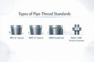
Understanding metric threads is essential for mechanical engineers, CNC machinists, and procurement specialists working across global supply chains. Governed by ISO standards (such as ISO 68-1, ISO 261, and ISO 965), ISO metric threads are the worldwide standard for mechanical fasteners, fluid fittings, and precision turned parts.
For teams accustomed to imperial sizing, working with metric thread dimensions often introduces friction in calculating pitch, converting dimensions from millimeters to inches, and identifying unlabelled parts. This engineering guide covers how to read metric thread sizes, calculate and measure pitch, use optical measurement tools, and reference standard sizes.
How to Read Metric Thread Size Callouts
A metric thread callout contains specific geometric parameters defining diameter, pitch, and tolerance.
Example: M10 × 1.25 - 6g
-
“M” (Designation): Indicates an ISO metric thread profile with a symmetrical 60° flank angle.
-
“10” (Nominal Major Diameter): The nominal crest diameter of an external thread (or the root of an internal thread), expressed directly in millimeters (10 mm).
-
“× 1.25” (Thread Pitch): The axial distance between adjacent crests, measured in millimeters. Standard coarse threads omit this value (e.g.,
M10automatically defaults to coarse pitch 1.5 mm). When a pitch is listed (like 1.25 or 1.0), it designates a fine metric thread. -
“6g” (Tolerance Class): Lowercase letters denote external threads (bolts, studs, threaded ports), while uppercase letters denote internal threads (nuts, tapped holes, e.g.,
6H).
 Metric Thread Dimensions: Pitch, TPI, and Inch-to-mm Conversion
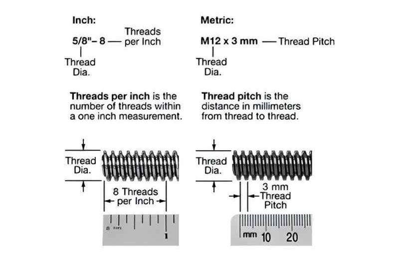
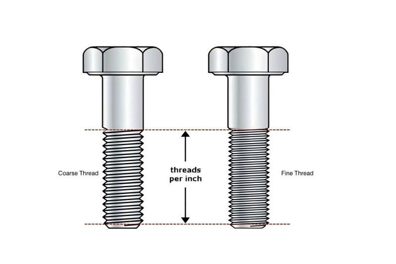
A frequent point of confusion between metric and imperial threads is the definition of thread spacing:
-
Metric Threads: Defined by Pitch (P), which is the physical distance (in mm) between consecutive thread crests.
-
Imperial/Unified Threads (UNC/UNF): Defined by Threads Per Inch (TPI), which counts the total number of crests within one axial inch.
Conversion Formulas
-
Converting TPI to Metric Pitch ($P$):Pitch (mm) = 25.4 / TPI
-
Converting Metric Pitch ($P$) to Equivalent TPI:Equivalent TPI = 25.4 / Pitch (mm)
-
Millimeters to Inches:Inches = Millimeters / 25.4Millimeters = Inches × 25.4
Because 1.0 mm equals 25.4 TPI, an M6×1.0 thread has 25.4 threads per inch. While a 1/4″-20 UNC bolt has a major diameter of 6.35 mm (close to 6 mm) and 20 TPI (equivalent to a 1.27 mm pitch), the physical mismatch in both diameter and pitch prevents these parts from mating without stripping or galling.
Metric Thread Chart: Coarse vs. Fine Pitch & Tap Drill Sizes
The table below outlines common ISO metric thread sizes, major diameters in millimeters and inches, standard coarse and fine pitch options, equivalent TPI ratings, and recommended tap drill diameters.
| Nominal Size | Major Diameter (mm) | Major Diameter (in) | Standard Coarse Pitch (mm) | Fine Pitch Options (mm) | Tap Drill Size – Coarse (mm) | Coarse Equivalent TPI |
| M3 | 3.00 | 0.1181 | 0.50 | 0.35 | 2.50 | 50.80 |
| M4 | 4.00 | 0.1575 | 0.70 | 0.50 | 3.30 | 36.29 |
| M5 | 5.00 | 0.1969 | 0.80 | 0.50 | 4.20 | 31.75 |
| M6 | 6.00 | 0.2362 | 1.00 | 0.75 | 5.00 | 25.40 |
| M8 | 8.00 | 0.3150 | 1.25 | 1.00, 0.75 | 6.80 | 20.32 |
| M10 | 10.00 | 0.3937 | 1.50 | 1.25, 1.00 | 8.50 | 16.93 |
| M12 | 12.00 | 0.4724 | 1.75 | 1.50, 1.25 | 10.20 | 14.51 |
| M14 | 14.00 | 0.5512 | 2.00 | 1.50, 1.00 | 12.00 | 12.70 |
| M16 | 16.00 | 0.6299 | 2.00 | 1.50 | 14.00 | 12.70 |
| M20 | 20.00 | 0.7874 | 2.50 | 2.00, 1.50 | 17.50 | 10.16 |
| M24 | 24.00 | 0.9449 | 3.00 | 2.00, 1.50 | 21.00 | 8.47 |
Quick Shop-Floor Formula for Tap Drill Size:Tap Drill Diameter (mm) ≈ Nominal Major Diameter (mm) – Pitch (mm)Example for M8 coarse: 8.0 mm – 1.25 mm = 6.75 mm (rounded to standard 6.8 mm drill bit).
How to Measure Metric Thread Pitch on a Bolt
Determining the exact pitch on an unlabelled bolt or threaded stud requires matching physical features against standard metrics using targeted measuring tools.
1. Using a Metric Pitch Gauge (Fastest Manual Method)
-
Select the gauge blade labeled with the suspected pitch (e.g., 1.25 mm, 1.50 mm).
-
Align the serrated teeth directly into the thread crests of the bolt.
-
Hold the assembly up against a light source. If no light passes between the gauge teeth and the thread flanks, the pitch is identified. If the teeth rock or leave visible gaps, test adjacent sizes.
2. Measuring with Calipers (When a Gauge Is Not Available)
-
Set digital vernier calipers to millimeters.
-
Measure across multiple thread peaks to minimize reading error. For example, span across 5 distinct thread crests.
-
Divide the measured distance by the number of thread spaces (4 spaces):Pitch (mm) = Span Distance / Number of Pitches
-
Compare this result to standard ISO metric pitches on the chart above.
Identifying Unknown Metric Threads: Measuring Thread Height, Pitch, and Diameter
When reverse-engineering an unknown bolt or machined fitting, rely on theoretical geometry to work backward to the nominal size.
Geometric Proportions of the 60° ISO Metric Profile
-
Theoretical Triangle Height:H = 0.866025 × Pitch
-
Basic Thread Flank Height (Engagement Depth):h = (5 / 8) × H ≈ 0.54127 × Pitch
Reverse-Calculation Steps
Step 1: Determine the Pitch ($P$)
Use a pitch gauge or optical profile to establish whether $P$ matches a standard metric step (such as 0.75, 1.0, 1.25, 1.5, or 2.0 mm).
Step 2: Measure External Major Diameter ($d$) or Internal Minor Diameter ($D1$)
-
For External Threads (Bolts/Studs): Use a digital caliper or micrometers. Because threads have negative manufacturing clearances (typically ISO 6g tolerance) to allow for smooth assembly and surface plating, your measurement will sit slightly below the integer nominal size. For example, an actual reading of 9.82 mm to 9.92 mm corresponds to an M10 thread.
-
For Internal Threads (Tapped Holes/Nuts): Measure the hole’s minor inner diameter with internal caliper jaws. Then calculate nominal diameter:Nominal Size ≈ Measured Bore Diameter + (1.08 × Pitch)Example: An internal bore measuring 8.5 mm with a 1.5 mm pitch indicates an M10 internal thread (8.5 + 1.5 = 10.0 mm).
Step 3: Measure Thread Height ($h$) with Optical Measuring Equipment
For damaged threads, thin-wall components, or complex turned parts, tactile calipers may introduce measurement errors. A 2.5D optical measuring machine (Profile Projector / Video Measuring System) provides non-contact visual verification:
-
The projected shadow profile magnifies the thread flank geometry.
-
Crosshair reticles calculate the true flank angle (confirming 60° versus 55° Whitworth/BSPP profiles).
-
Edge-detection tools capture the true crest-to-root height ($h$) and check for thread root radiusing and crest truncations.
Quality Inspection and Tolerance Control
Maintaining consistent metric thread tolerances across batch production requires dedicated inspection workflows:
-
Go / No-Go Thread Plug & Ring Gauges:
-
Go Gauge: Must spin down the entire length of the thread without binding.
-
No-Go Gauge: Must not engage beyond two full rotations.
-
-
Three-Wire Method:
-
Used with a high-accuracy outside micrometer to measure the pitch diameter ($d2$), isolating pitch diameter errors from crest truncation or burrs.
-
-
Plating Allowances:
-
If a steel component undergoes electro-galvanizing, zinc-nickel plating, or electroless nickel plating (typically adding 5 μm to 12 μm per side), external thread pitch diameters must be machined to the lower bound of tolerance class 6g (or 6e) to prevent thread interference post-plating.
-
Frequently Asked Questions (FAQ)
What is the standard pitch for an M10 thread?
The standard coarse pitch for an M10 thread is 1.5 mm. Fine pitch options include 1.25 mm and 1.0 mm. When a technical drawing specifies only “M10”, standard coarse (1.5 mm) is required.
Can an M8 bolt thread into a 5/16″ UNC tapped hole?
No. An M8 bolt has a nominal outer diameter of 8.00 mm (0.3150″) and a standard coarse pitch of 1.25 mm (20.32 TPI). A 5/16″-20 UNC fastener has an outer diameter of 7.94 mm (0.3125″) and exactly 20 TPI (1.27 mm pitch). Although dimensions appear close, threading them together causes cross-threading and thread seizure after 1 to 2 turns.
How can you distinguish a metric thread from a unified (UNC/UNF) thread?
First, check the thread angle: both metric and UNC/UNF share a 60° flank angle. Next, measure the crest pitch: metric threads align with even millimetric increments (1.0, 1.25, 1.5 mm), whereas imperial threads match integer TPI counts (e.g., 18, 20, 24 threads per inch). Finally, verify with dedicated metric and inch pitch gauges or a 2.5D optical comparator.

Custom Precision Metric Thread Machining Services
Achieving precise thread fits across CNC turned parts, hydraulic adapters, and specialized mechanical fittings requires tight machine calibration, quality cutting inserts, and disciplined metrology.
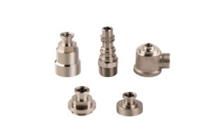
At Yuhuan Hongqian Machinery Co., Ltd., we operate an ISO 9001-certified manufacturing facility equipped with over 70 CNC lathes, multi-axis turning centers, and automated gantry handling systems. We manufacture custom external and internal metric threaded parts across stainless steel (SS304, SS316), carbon steel (1215, 1045), brass, and aluminum.
-
Tolerances: Controlled to ISO 6g / 6H, 4h, or custom drawing requirements down to ±0.01 mm on pitch diameters.
-
Metrology: Every production batch is verified using thread ring/plug gauges, 2.5D optical projectors, and surface roughness testers.
-
Surface Finishes: Chemical nickel, zinc plating, passivation, and custom protective coatings with verified pre-plate thread allowances.
Need precision metric threaded components manufactured to tight tolerances?
Contact us Upload your 2D/3D drawings (STEP, CAD, or PDF) to our engineering team today for design-for-manufacturing (DFM) feedback and a competitive quote within 24 hours.