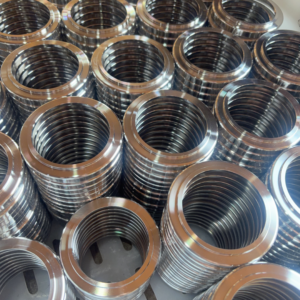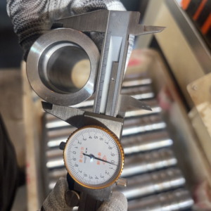
When engineering custom fluid components, determining whether to route a part through CNC milling vs turning directly influences cycle time, dimensional stability, surface finish, and unit cost. While both methods fall under precision subtractive manufacturing, the core mechanical difference is straightforward: turning rotates the workpiece against a stationary single-point cutting tool to generate cylindrical profiles, whereas milling spins a multi-point rotary cutter against a stationary or translating workpiece to generate prismatic features, pockets, and planes.
At Yuhuan Xinghe Machinery Factory, our production floor specializes in high-precision CNC turning, Swiss-type turning, and multi-axis mill-turn centers for custom pipe fittings, bulkheads, and hydraulic adapters. Below, we break down the fundamental kinematic distinctions between lathes and milling machines, how live tooling bridges the gap, and how to optimize your part geometry for the most cost-effective manufacturing process.
Core Mechanics: Lathe vs. Milling Machine
Understanding the kinematic principles of a lathe vs milling machine helps mechanical designers define sensible tolerances and select appropriate raw stock profiles (such as hexagonal bar stock, round bars, or square billets).
| Machining Factor | CNC Turning (Lathe) | CNC Milling (Mill) |
|---|---|---|
| Kinematic Action | Workpiece rotates at high RPM; cutting tool feeds along X and Z axes. | Workpiece remains fixtured to the machine bed; cutting tool rotates at high RPM. |
| Cutting Tool Type | Single-point cutting tool (continuous contact during material removal). | Multi-point rotary tool (end mills, face mills; intermittent contact). |
| Primary Raw Stock | Round bar stock, hexagonal bars (standard for fitting bodies), extruded tubing. | Square blocks, rectangular plates, cast billets, complex unmachined forgings. |
| Geometric Profiles | Rotational symmetry: cylindrical, conical, internal bores, external threads. | Prismatic features: flat faces, slots, pockets, deep contours, stepped planes. |
| Surface Roughness (Ra) | Uniform circular lay, exceptional concentricity (Ra 0.4 to 1.6 um typical). | Scallop or fly-cut tool marks depending on stepover and feed rates. |
| Chip Formation | Continuous or tightly curled ribbons managed by insert chip-breaker geometry. | Discontinuous, interrupted chips created by individual flutes entering the cut. |
How CNC Turning Machining Operates
In standard turning machining, a hydraulically actuated chuck or precision collet grips the raw bar stock inside the headstock spindle. As the spindle drives the stock up to programmed speeds, single-point carbide inserts profile the outer diameter (OD), bore out the inner diameter (ID), cut sealing bevels, and single-point threads (such as NPT, BSPT, Metric, or UNF).
Because the part spins on its central axis, CNC turning ensures concentricity and perpendicularity across critical fluid passages. For parts like stainless steel hex nipples, bulkhead fittings, and hose barbs, turning is the most natural process because high axial concentricity prevents fluid bypass under pressure.
- Continuous Engagement: The single-point insert maintains uninterrupted engagement with the turning diameter, eliminating the micro-vibrations common to interrupted cuts.
- Dual-Spindle Efficiency: Multi-axis turning centers feature main and sub-spindles. The primary spindle cuts the front thread and external hex, then automatically hands off the part to the sub-spindle for back-side boring, chamfering, and internal threading, dropping a 100% complete part off the machine without secondary handling.
Engineering Review Tip: Wondering whether your custom fitting requires dedicated mill setup or can be turned complete on a lathe with live tooling? Consult our CNC machining engineers to evaluate tool paths, reduce cycle times, and prevent secondary clamping errors.
How CNC Milling Operates
CNC milling setups rigidly lock the workpiece onto a T-slot bed, vacuum fixture, or hydraulic vise. The spindle carries multi-flute end mills, ball-nose cutters, or face mills, translating along the X, Y, and Z axes (and additional A/B rotational axes in 4-axis and 5-axis machines).
Milling excels at prismatic configurations: manifold blocks, mounting brackets, pump bodies, and structural housings. Because the cutting edge encounters the material intermittently, milling creates interrupted chip loads. This requires rigid fixturing and carefully calculated feeds and speeds to avoid chatter, especially when machining work-hardening stainless steels like 304 or 316L.
Milled Features on Turned Parts: The Power of Live Tooling
Modern machine shops frequently blur the line between mill vs lathe through turn-mill centers and live-tooled CNC lathes. When producing industrial fluid fittings from solid round or hex bar, parts rarely feature purely cylindrical geometries. They often require:
- Wrench flats on rounded valve bodies for field assembly
- Cross-drilled cross-ports or bleed holes perpendicular to the bore
- Off-center mounting bolt patterns
- Lock-pin slots or retention grooves
Equipping a CNC lathe with driven (live) tooling allows the spindle to index and lock at precise angular orientations (C-axis positioning). The rotary tool then mills the flat or drills the radial hole right in the turning envelope. This single-setup process eliminates the dimensional stacking and concentricity errors caused by unchucking a part and moving it to a secondary milling machine.

DFM Selection Guide: When to Turn vs. When to Mill
To keep production budgets reasonable and delivery lead times tight, design engineers should align part geometry with the optimal machine platform:
- Choose CNC Turning when: The component is rotationally symmetric, requires continuous single-point threads (NPT/BSPP), demands runout control under 0.02 mm between sealing faces, or is sourced from round or hex bar stock up to 80 mm diameter.
- Choose CNC Milling when: The finished geometry is predominantly cubical, features multiple perpendicular mounting holes, asymmetrical cavities, or requires contoured clearance pockets.
- Choose Turn-Mill / Live Tooling when: The core profile is round or hex with localized flats, radial cross-bores, or keyways. This avoids dedicated milling setups and lowers unit costs at volume.
FAQ: Milling vs. Turning in Precision Machining
Can a CNC lathe produce square or hexagonal features?
Yes. By feeding raw hexagonal bar stock directly through an automated bar feeder, the external hex profile is already formed. Alternatively, if machining from solid round stock, a CNC turning center equipped with driven live tooling can mill the flats via C-axis interpolation while the part remains chucked.
Is CNC turning faster and cheaper than CNC milling?
For cylindrical and concentric parts, turning is significantly faster and more economical. Bar feeders automate material indexing, cutting tools maintain continuous engagement, and cycle times for fittings are measured in seconds rather than minutes. Milling involves more complex tool changes, multi-face repositioning, and higher fixture costs.
What tolerances can be achieved on CNC turned pipe fittings?
On our precision CNC lathes, critical sealing diameters, O-ring groove widths, and thread pitch diameters are consistently held to ±0.01 mm (±0.0004 in). Commercial external features are maintained within standard ±0.02 mm parameters.
Why is continuous cutting in turning beneficial for stainless steel?
Stainless steels (such as SS316L and 304) tend to work-harden rapidly under repeated tool impacts. Turning keeps the cutting edge submerged beneath the cut surface, leading to smoother tool wear, longer insert life, and superior surface finishes compared to the repeated impact shock of milling flutes.
Send Your Drawings to Xinghe for a Rapid DFM & Manufacturing Quote
Have an upcoming fluid system project requiring precision CNC turned components or custom pipe fittings? Send your 2D PDF, DWG, or 3D STEP/IGES CAD files to the engineering team at Yuhuan Xinghe Machinery Factory. We will review your tolerances, thread specifications, and material selections, providing a comprehensive DFM assessment and formal quotation within 24 hours.