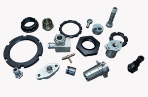
What Are Different Types of Hydraulic Fittings for Identification?
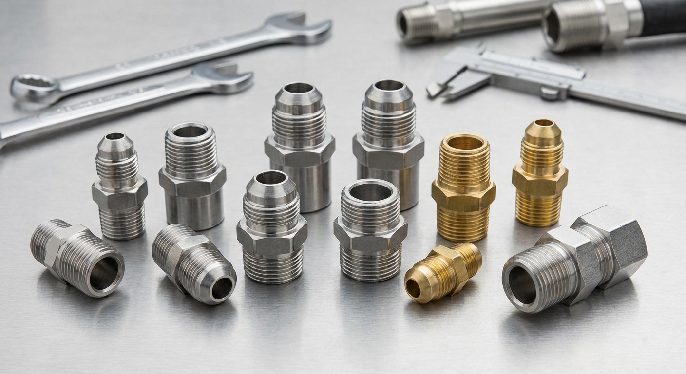
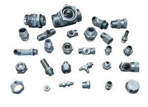
Identifying different types of hydraulic fittings begins with analyzing the thread style, sealing surface, and the material of the connector. Most identification processes involve using calipers to measure the outside diameter and pitch gauges to determine the thread count.
Determining Thread Standards
You must first look at the shape of the threads to see if they are tapered or parallel. But there is more to the process than just a visual inspection.
- Tapered threads seal through metal-to-metal interference.
- Parallel threads require an O-ring or washer to create a fluid-tight barrier.
- Metric threads are measured in millimeters, while American threads use inches.
Inspecting Sealing Surfaces
When you examine a connector, the angle of the seat tells you everything about its compatibility. Here is the deal: if you mix a 37-degree flare with a 45-degree seat, you will experience immediate failure.
- Look for the presence of an O-ring groove on the face or base.
- Identify if the seal is made on the threads or a machined flare.
- Check for damage or pits on the mating surfaces that could bypass the seal.
Selecting the right connector requires a systematic approach to measuring both the physical dimensions and the internal sealing geometry. By matching these characteristics to international standards, you ensure a secure and leak-free installation.
| Tool | Measurement | Objective |
| Caliper | Thread Diameter | Establish nominal size |
| Pitch Gauge | Threads Per Inch | Identify standard |
| Seat Gauge | Flare Angle | Match mating parts |
The following analysis helps you distinguish between tapered and straight thread designs for optimal pressure retention.
Why Use NPT and NPSM Hydraulic Fittings?
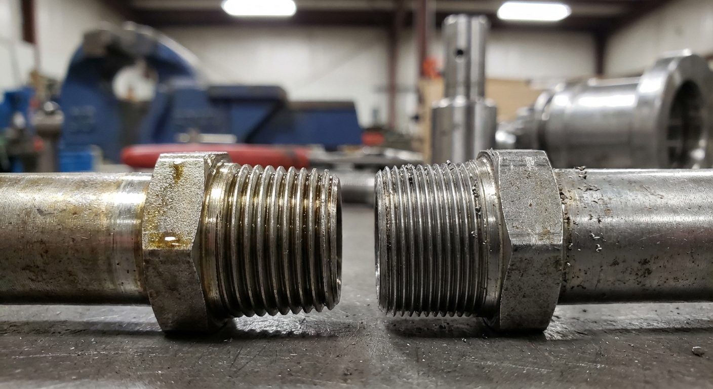
NPT and NPSM thread hydraulic fittings are used because they provide a reliable, cost-effective connection for low-to-medium pressure systems. These American standards have been the backbone of industrial plumbing for decades due to their simplicity and availability.
Tapered Thread Deformation
You will find that NPT threads are designed to “crush” together as you tighten them, filling the gaps between the crests and roots. Believe it or not, this deformation is what actually creates the primary seal.
- Apply thread sealant or Teflon tape to ensure a leak-free fit.
- Use NPTF “Dry-Seal” versions for fuel systems to minimize sealant needs.
- Avoid over-tightening, as it can crack the female port of the housing.
Mechanical Straight Thread Seals
If you require a connection that can be frequently disassembled without damage, NPSM is your best option. You should note that these threads do not seal on the threads themselves but on an internal 30-degree seat.
- Pair a straight male thread with a female swivel for easy installation.
- Ensure the male end has a 30-degree internal chamfer.
- Rely on mechanical compression rather than thread interference for the seal.
While NPT is excellent for permanent installations, NPSM offers the flexibility of a swivel connection for easier maintenance and routing. Choosing between them depends on whether you need a permanent seal or a reusable mechanical joint.
| Connection | Sealing Method | Best Use |
| NPT | Thread Interference | Permanent plumbing |
| NPSM | 30° Inverted Seat | Swivel hose ends |
| NPTF | Metal-to-Metal | Fuel and oil transfer |
This comparison clarifies how thread geometry dictates the assembly method and long-term durability of the joint.
How Do JIC and Flare Hydraulic Fittings Seal?
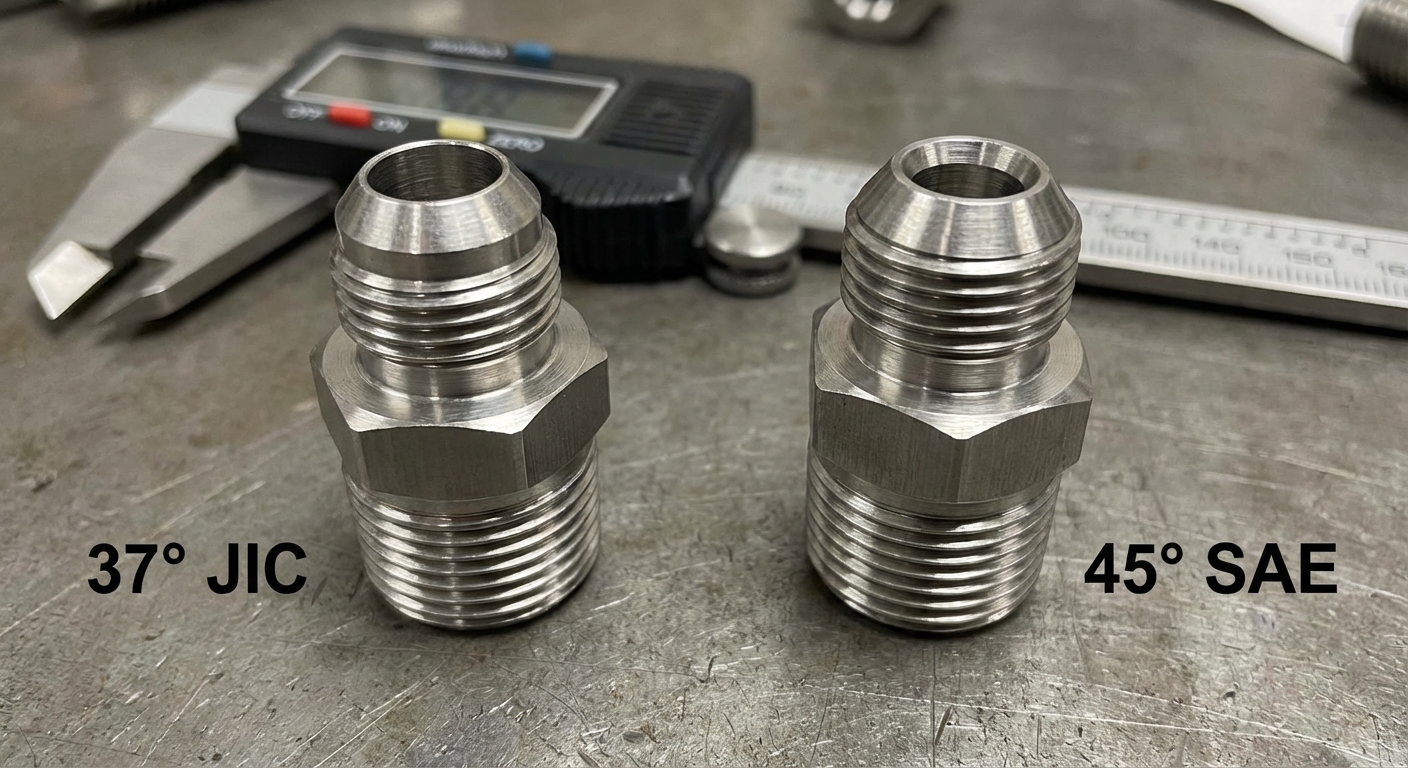
JIC and SAE flare hydraulic fittings seal by establishing metal-to-metal contact between a male flare and a female cone. This mechanical connection is highly valued in high-pressure environments because it does not rely on elastomers that can degrade over time.
The 37-Degree JIC Advantage
You will most likely encounter JIC fittings in heavy machinery and construction equipment. But there is more; these connectors are designed to be high-strength and highly resistant to pressure spikes.
- Maintain the 37-degree angle to ensure a perfect mating surface.
- Benefit from the ability to reuse the fitting multiple times.
- Use steel or stainless steel materials for maximum pressure ratings.
Automotive 45-Degree Standards
When you work on refrigeration or light truck systems, you will often see the 45-degree flare standard. Here is the deal: although they look similar to JIC, they are absolutely not interchangeable.
- Identify these by their brass construction in many low-pressure applications.
- Prevent cross-contamination by keeping 37 and 45-degree parts separate.
- Use these for soft tubing like copper or aluminum where flaring is easy.
Flared connections provide a robust solution for systems where vibration is common, as the metal seat remains stable under stress. Ensuring the seat angle is correctly matched is the most critical step in preventing immediate leaks.
| Flare Type | Seat Angle | Standard |
| JIC | 37 Degrees | SAE J514 |
| SAE Flare | 45 Degrees | SAE J512 |
| Inverted Flare | 42/45 Degrees | Automotive |
Understanding flare angles prevents the most common technician error: intermixing incompatible mechanical seats.
When to Choose ORFS Hydraulic Fittings?
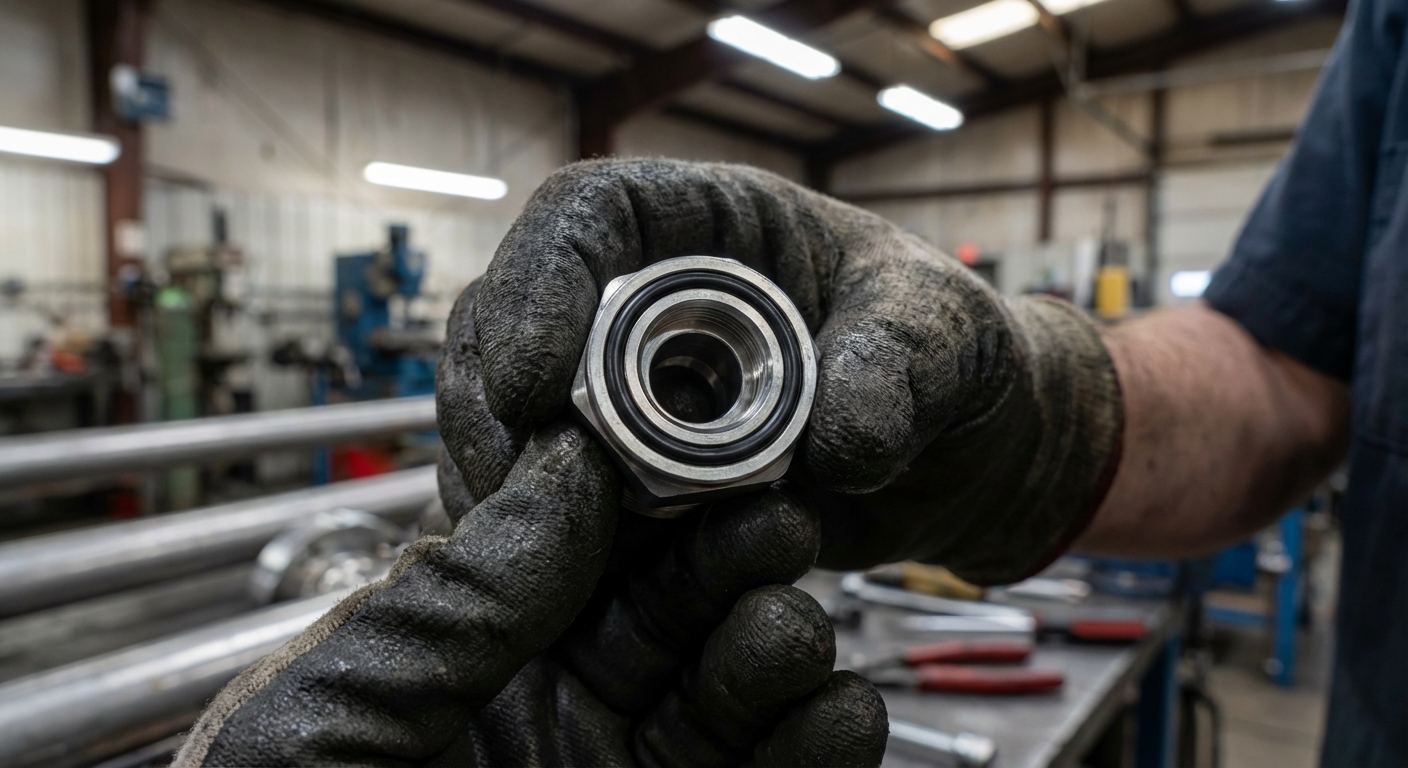
Choosing ORFS hydraulic fittings is necessary when you are dealing with high-vibration systems that require a “zero-leak” performance. These fittings use an O-ring located in the face of the male connector to provide a superior seal compared to metal-to-metal designs.
Zero-Clearance Installation
You can install ORFS fittings in extremely tight spaces because they do not require you to pull the tubing back to seat the connection. But there is more to the design than just convenience.
- Slide the flat female face directly over the male O-ring.
- Avoid the risk of over-flaring or cracking tubes during assembly.
- Replace only the O-ring if a leak occurs, saving the entire fitting.
High Vibration Resistance
If your machinery experiences constant shock, the O-ring face seal will absorb these movements without loosening. Here is the deal: the elastomer compresses to fill every microscopic void, even under intense pressure.
- Select Buna-N or Viton O-rings based on your fluid compatibility.
- Inspect the groove for debris before you finalize the connection.
- Ensure the flat face of the female is free from deep scratches.
The O-ring face seal is widely considered the best design for modern hydraulic systems where environmental protection and leak prevention are top priorities. It offers a forgiving installation process while maintaining a world-class seal.
| Component | Role | Maintenance |
| Male ORFS | Holds O-ring in face | Clean the groove |
| Female ORFS | Mating flat surface | Check for pitting |
| O-Ring | Primary seal barrier | Replace if brittle |
The following section explains why straight threads with O-rings are preferred for port connections over tapered alternatives.
What Are the Benefits of ORB Hydraulic Fittings?

ORB hydraulic fittings provide a superior seal in medium-to-high pressure ports by combining straight threads with a high-quality elastomer O-ring. This design is highly recommended by the NFPA for preventing “weeping” leaks that often plague tapered pipe connections.
Eliminating Port Leaks
You will achieve a much more reliable seal with ORB because the O-ring is compressed into a machined chamfer at the base of the port. But there is more; the straight threads handle the mechanical load while the O-ring handles the fluid.
- Lubricate the O-ring during installation to prevent pinching.
- Achieve a seal without having to over-torque the fitting.
- Enjoy a cleaner system with no need for messy thread tapes.
Mechanical Strength Advantage
When you use ORB, the straight threads provide consistent engagement throughout the entire depth of the port. Here is the deal: this allows the fitting to handle pressure spikes and surges far better than tapered designs.
- Use these in aluminum or steel manifolds for high durability.
- Match thread sizes to SAE J1926 standards for global compatibility.
- Identify the spotface to ensure the O-ring has a flat surface to seat against.
Straight thread O-ring boss connections represent the modern standard for hydraulic valve and cylinder ports. They offer a repeatable, high-pressure seal that simplifies both initial assembly and later maintenance.
| Feature | Specification | Benefit |
| Thread Type | Straight (UN/UNF) | High mechanical grip |
| Sealing | O-Ring at base | No weeping leaks |
| Standard | SAE J1926 | Global interchangeability |
By utilizing ORB connectors, you ensure that the most vulnerable part of your system—the port connection—remains bone-dry.
How Do Flange Hydraulic Fittings Manage Pressure?
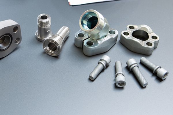
Flange hydraulic fittings manage pressure by distributing the clamping force across four heavy-duty bolts, which prevents the distortion common in threaded connections. They are the preferred choice for high-flow and high-pressure lines where traditional fittings would be too difficult to tighten.
Code 61 and Code 62 Differences
You must distinguish between the standard Code 61 and the high-pressure Code 62 series to ensure safety. But there is more; although the bolt patterns look similar, the dimensions are slightly larger for higher pressure ratings.
- Use Code 61 for pressures up to 3,000 or 5,000 PSI depending on size.
- Deploy Code 62 for 6,000 PSI heavy-duty applications.
- Measure the bolt hole spacing precisely to identify the correct series.
Ease of Large Hose Assembly
If you are working with large-diameter hoses, you will find that flanges make your job much easier. Here is the deal: you don’t have to rotate a massive hose end; you simply bolt the flange head to the port.
- Utilize split flanges for maximum flexibility in tight spaces.
- Ensure the O-ring is seated correctly in the flange head groove.
- Tighten the four bolts in a cross pattern for even pressure.
Flange connections provide a robust and vibration-resistant seal for the most demanding parts of a hydraulic circuit. They allow for easy maintenance of large components without the need for massive wrenches.
| Flange Type | Pressure Rating | Primary Application |
| Code 61 | Standard (up to 5k) | General Industrial |
| Code 62 | High (6,000 PSI) | Heavy Mining/Oil |
| Square Flange | High (JIS) | Japanese Machinery |
The following breakdown assists in identifying European metric standards that differ significantly from American sizes.
What Are the Metric and DIN Hydraulic Fittings?
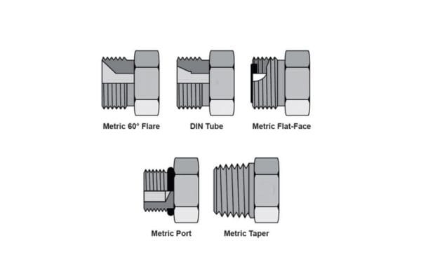
Metric and DIN hydraulic fittings are the standard connectors for European-made machinery, featuring a 24-degree cone seat and metric threads. These systems are highly versatile, supporting both “bite-type” compression for raw tubing and O-ring seals for hose ends.
The DIN 2353 Bite Concept
You can create a permanent, leak-proof joint on steel tubing using a nut and a cutting ring (ferrule). But there is more; as you tighten the nut, the ferrule “bites” into the tube surface to create a mechanical grip.
- Use the Light (L) series for medium-pressure hydraulic circuits.
- Select the Heavy (S) series for extreme high-pressure environments.
- Ensure the tube is cut square and deburred for a proper bite.
DKO Style Sealing
When you need extra security, you should look for DKO style fittings which incorporate an O-ring into the 24-degree cone. Here is the deal: this dual-seal approach provides both a metal-to-metal and an elastomeric barrier.
- Identify these by the O-ring visible on the male nose.
- Enjoy better performance in systems with extreme temperature cycles.
- Benefit from a fitting that is less sensitive to slight under-torquing.
Metric standards are essential for any global operation, as they dominate the agricultural and transport equipment markets outside of North America. Mastering these sizes is the key to maintaining diverse equipment fleets.
| Series | Pressure Level | Typical Thread |
| LL | Extra Light | Pneumatic/Low Oil |
| L | Medium | General Hydraulics |
| S | High | Heavy Duty Systems |
This technical overview ensures you can correctly source European parts without the risk of cross-threading.