In industrial fluid transmission and mechanical design, choosing between a hose fitting and a pipe fitting directly determines system sealing integrity, pressure tolerance, and service lifespan. Engineers, mechanics, and procurement specialists frequently evaluate hose fittings versus rigid pipe and pipe fittings when configuring pneumatic lines, hydraulic circuits, or high-pressure water systems.
Mismatched fluid fittings lead to persistent fluid leakage, unexpected pressure drops, costly downtime, and severe workplace safety hazards. This comprehensive engineering guide breaks down the core differences between flexible hose to hose fittings and rigid fittings piping setups, examining media compatibility, step-by-step field assembly, fundamental geometries, thread standards (NPT vs. GHT), and precision manufacturing quality control powered by CNC machinery, CNC turning, and tight-tolerance CNC lathe parts.
Core Definitions: Hose Fitting vs. Pipe Fitting
What is a Hose Fitting?
A hose fitting (commonly referenced as a flexible fitting hose or water hose fittings) is an engineered connector designed to join flexible tubing—such as rubber, polyurethane (PU), PTFE, silicone, or wire-braided hydraulic hoses—to auxiliary equipment, pumps, valves, or other hoses (hose to hose fittings). Its primary engineering purpose is to facilitate continuous, leak-free flow while accommodating dynamic motion, structural vibration, and regular maintenance cycles.
What is a Pipe Fitting?
A pipe fitting (widely cataloged across industrial pipe & fitting or fittings pipe systems) is designed to couple rigid, non-flexible conduits such as stainless steel, brass, copper, carbon steel, or rigid UPVC pipes. Pipe fittings establish permanent or semi-permanent mechanical connections where structural rigidity, extreme thermal resistance, and maximum burst pressure containment are required.
Quick Comparison Matrix: Hose Fittings vs. Pipe Fittings
| Evaluation Feature | Hose Fitting | Pipe Fitting |
| Conduit Compatibility | Flexible hoses (Rubber, PU, PTFE, Reinforced) | Rigid pipes (Stainless steel, Brass, Carbon steel, PVC) |
| Vibration & Dynamic Motion | Extremely High (Buffers pulses, strokes, and flex) | Very Low (Susceptible to fatigue failure without expansion loops) |
| Pressure Ratings | Low to high (Governed by hose braid and crimp specs) | Medium to ultra-high (Dependent on wall thickness and forging) |
| Assembly & Servicing | Fast, modular, ideal for rapid routing and disconnects | Rigid installation requiring precise alignment, threading, or welding |
| Primary Industry Use | Hydraulic excavators, automation robotics, washdown lines | Chemical plant headers, steam circuits, municipal utility mains |
Sealing Mechanisms & Connection Types
Fluid containment methods differ significantly between flexible hose assemblies and rigid pipe networks.
Hose Fitting Sealing Types
1. Barbed Stems (Hose Barb)
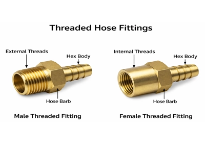
Hose barb fittings feature continuous, raised radial ridges that slide into the pliable inner core of a flexible hose. When an external worm-gear clamp or punch-lock band is torqued down, the elastomeric tube compresses into the barb valleys, generating a tight circumferential friction seal.
2. Crimped & Swaged Sleeves
Standard for high-pressure hydraulic and industrial fluid transfer. A ductile metal outer collar is placed over the hose end and compressed radially using a calibrated hydraulic crimper. The collar deforms into the wire-reinforcement layers, providing mechanical interlock capable of holding pressures exceeding 40 MPa (400 bar).
3. Push-to-Connect & Quick Disconnect Couplings
Commonly specified in pneumatic control lines and automated fluid testing rigs. These utilize an internal stainless-steel gripping collet and a precision O-ring (NBR, EPDM, or FKM). Tubing locks instantly upon insertion, while depressing the release ring allows tool-free disassembly.
Pipe Fitting Sealing Types
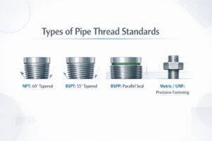
1. Tapered Thread Joints (NPT / BSPT)
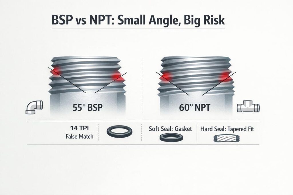
Machined with a 1:16 taper. As male and female threads engage, interference along the thread flanks creates a solid mechanical wedge. PTFE thread sealing tape or anaerobic paste fills the microscopic root-and-crest clearances to prevent spiral leakage.
2. Parallel Thread Mechanical Joints (BSPP / Metric ISO)
Straight cylindrical threads provide pure axial clamping force. Fluid sealing occurs at the shoulder against a flat counterbore face using a bonded washer (Dowty seal), copper crush ring, or recessed elastomeric O-ring.
3. Compression & Twin-Ferrule Fittings
Widely utilized in high-purity gas panels and instrumentation systems. Tightening the compression nut drives a front ferrule into the fitting body and swages a rear ferrule radially into the outer surface of the rigid metal tube, achieving a metal-to-metal seal rated up to 10,000 PSI without hot work.
4. Socket-Weld & Butt-Weld Connections
Permanent, non-demountable joints formed by circumferential fusion welding. Ideal for extreme thermal cycling, superheated steam, and toxic chemical headers where zero mechanical leakage is mandatory.
Critical Thread Standards: Pipe Thread (NPT) vs. Hose Thread (GHT)
Technicians and plant operators often ask about thread interoperability across fluid systems.
Is Hose Thread the Same as Pipe Thread?
No, hose thread is fundamentally different from pipe thread. They cannot be interchanged or directly mated. Pipe threads rely on tapered metal flank interference or shoulder gaskets to seal industrial fluid lines, whereas garden hose threads use straight threads solely to draw an internal elastomeric washer against a flat sealing face.
Is 3/4 Pipe Thread the Same as Hose Thread?
No, 3/4″ pipe thread (NPT) is not the same as 3/4″ hose thread (GHT). While both share a nominal 3/4-inch designation, their dimensions and pitch configurations are distinct:
-
3/4″ NPT (National Pipe Taper): Features 14 threads per inch (14 TPI) with a 60° thread flank angle cut on a 1:16 taper. Sealing is achieved via thread interference along with PTFE tape or paste.
-
3/4″ GHT (Garden Hose Thread): Features 11.5 threads per inch (11.5 TPI) with parallel (straight) threads and a standardized 1.0625-inch outer diameter. Sealing relies entirely on compressing a flat rubber washer inside the female socket.
Are NPT and GHT Compatible?
No, NPT and GHT are strictly incompatible.
Due to the pitch mismatch (14 TPI vs. 11.5 TPI), attempting to thread an NPT pipe fitting directly into a GHT hose fitting results in cross-threading after 1 to 2 turns. Forcing the connection with a wrench strips the brass or plastic threads and prevents proper compression against the sealing washer, causing immediate fluid blowout under pressure. Connecting them requires a dedicated, precision-machined NPT to GHT brass adapter.
Media Compatibility Breakdown (Media Comparison)
Fitting selection must account for the chemical nature, abrasive particle load, and operating temperature of the fluid media:
| Media Category | Hose Fitting Performance | Pipe Fitting Performance | Engineering Recommendation |
| Hydraulic & Lube Oils | Excellent. Pairs with reinforced flexible hoses for dynamic cylinder motion. | Excellent. Ideal for static high-pressure main lines between pumps and manifolds. | Use flexible hose fittings at moving actuators; use rigid pipe fittings on static headers. |
| Compressed Air & Inert Gases | Excellent. PU hoses paired with push-in fittings yield fast pneumatic response. | Good. Standard for plant-wide compressed air ring mains and drops. | Use quick-connect hose fittings at workstations and rigid aluminum/steel pipe for mains. |
| High-Temp Steam (≥180°C) | Restricted. Standard rubber and PU degrade rapidly; requires metal braided hose. | Superior. Forged carbon steel and stainless fittings handle high thermal loads. | Always specify rigid metal pipe fittings for high-pressure, high-temperature steam lines. |
| Corrosive Acids & Alkalis | Good. Requires virgin PTFE (Teflon) liners and specialized alloy fittings. | Superior. 316L stainless steel or Hastelloy pipe fittings provide zero permeation. | Prefer rigid 316L stainless steel pipe fittings for permanent aggressive chemical lines. |
| Slurries & Powders | Good. Elastomeric inner liners absorb abrasive impact from solid particles. | Fair. Direction changes in rigid elbows risk localized erosion and wall thinning. | Use large-bore abrasion-resistant flexible hose fittings for slurry transfer. |
Step-by-Step Field Assembly & Installation
Hose Fitting Assembly Procedures
1. Hose Barb & Clamp Assembly
-
Square Cut: Cut the flexible hose cleanly and perpendicularly using a dedicated hose cutter.
-
Pre-position Clamp: Slide the worm-gear or T-bolt clamp over the hose end.
-
Insert Barb: Push the barbed stem fully into the hose until the hose end seats flush against the fitting shoulder (use a water-soluble lubricant if necessary).
-
Torque Clamp: Position the clamp centered over the barbs and torque to manufacturer specifications. Avoid over-tightening, which can pinch and fracture the outer rubber cover.
2. High-Pressure Crimped Hydraulic Fitting Assembly
-
Skive Hose (If Specified): Strip the outer cover down to the wire reinforcement based on manufacturer specifications.
-
Position Ferrule & Stem: Slide the outer metallic crimp collar over the hose and push the stem fully into the inner core.
-
Radial Crimping: Insert the assembly into a calibrated CNC hydraulic crimper, crimp to the target crimp diameter, and verify dimensions using a vernier caliper.
Pipe Fitting Assembly Procedures
1. Threaded Pipe Joint Assembly (NPT / BSPT)
-
Inspection & Cleaning: Inspect male and female threads, ensuring surfaces are free of burrs, dirt, and metal shavings.
-
Apply Sealant: Wrap PTFE tape clockwise (in the direction of the thread spiral) 2 to 3 turns, or apply anaerobic paste sealant.
-
Engagement & Torque: Thread hand-tight for 2 to 3 turns, then use two wrenches to tighten 1.5 to 3 turns past hand-tight. Avoid over-torquing, which can split female cast ports.
2. Twin-Ferrule Compression Tube Fitting Assembly
-
Tube Prep: Cut the rigid tube square, deburr inner and outer edges, and clean the tube OD.
-
Full Insertion: Slide the nut, rear ferrule, and front ferrule onto the tube, and insert the tube into the fitting body until it bottoms out on the internal shoulder.
-
Final Pull-Up: Tighten the nut finger-tight. Hold the fitting body stationary and rotate the nut exactly 1-1/4 turns (1.25 turns) with a wrench to swage the ferrules into the tube.
Fundamental Geometries & Flow Routing
What are the Four Types of Fittings?
In fluid piping and hose system design, the four fundamental fitting types categorized by layout geometry and flow distribution are:
-
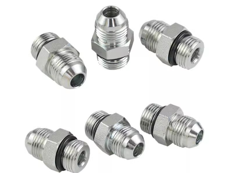
Straight Fittings (Union / Hex Nipple / Reducer): Extend collinear conduits in a straight line or adapt between different port sizes. Straight hose fittings often feature bulkhead locknuts for cabinet pass-throughs.
-
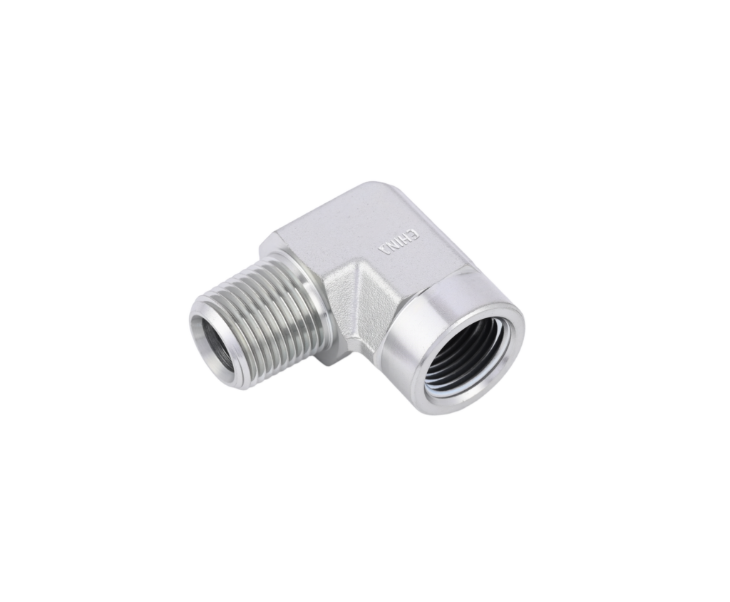
Elbow Fittings (90° and 45° Elbows): Alter flow direction by 90° or 45°. In flexible systems, 90° elbows prevent hose kinking and preserve minimum bend radii; in rigid piping, they navigate around structural framing.
-
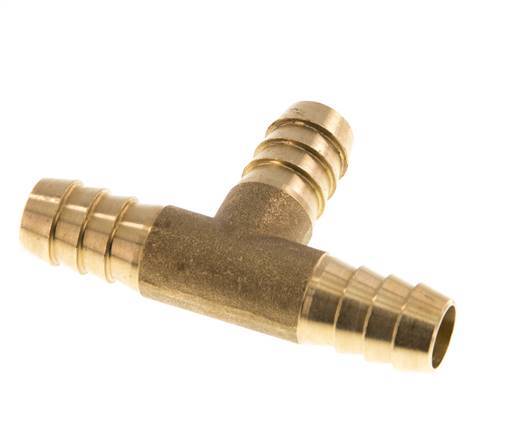
Tee Fittings (T-Type and Y-Type Tees): Split one inlet stream into two branch outlets, or combine two return lines into a single header. Y-tees (laterals) reduce turbulence and dynamic pressure drop compared to standard 90° Ts.
-
Cross Fittings (4-Way Crosses): Provide four intersecting fluid ports at 90° intervals for multi-directional distribution in compact manifolds and air distribution headers.
Precision Manufacturing: Blank Forming & CNC Machinery
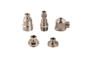
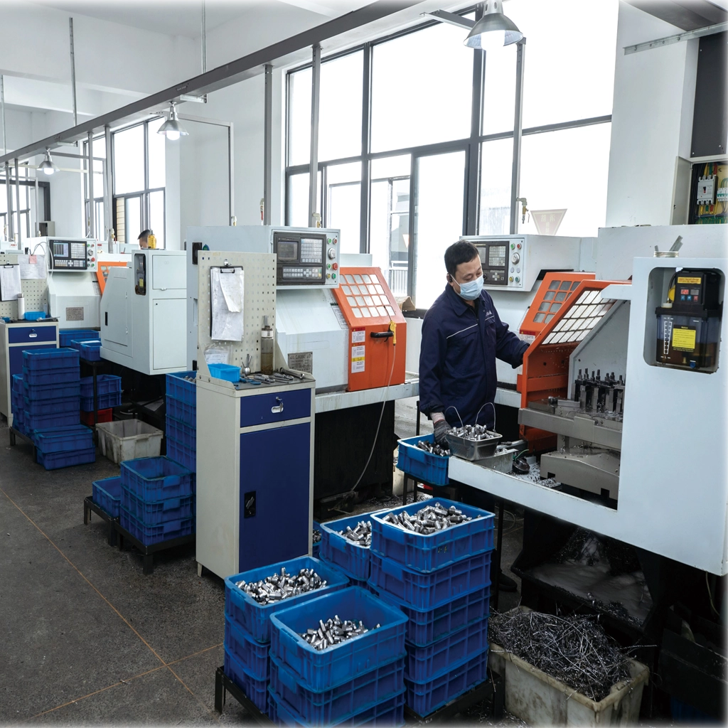
The operational reliability of any fluid connector depends on raw material metallurgical density and precision machining. High-grade production of both hose fittings and pipe fittings relies on advanced CNC machinery, CNC turning, and tight-tolerance CNC lathe parts.
-
Near-Net Blank Forming: Blanks for straights, elbows, and tees are formed using cold heading, hot forging (red punching), or silica sol investment casting. These methods align internal metallurgical grain flow, eliminate casting porosity, and elevate burst pressure thresholds.
-
Precision CNC Turning: Multi-axis CNC lathes machine critical sealing seats (JIC 37°, DIN 24°, O-ring grooves) and single-point threads (NPT, BSPP, Metric). Machining achieves surface roughness of Ra 0.4 to Ra 0.8 μm and dimensional tolerances within ±0.01 mm, guaranteeing zero-leak metal-to-metal seating.
Total Cost of Ownership (TCO) in Fitting Selection
Evaluating fittings solely on initial piece price often results in higher lifecycle expenses. A robust procurement strategy assesses Total Cost of Ownership (TCO):
| Cost Dimension | Definition & Failure Mechanism | Operational & Financial Impact | Engineering Mitigation Strategy |
| Initial Purchase Price | Direct per-unit machining and procurement cost of raw fittings. | Accounts for only 15%–25% of the cumulative lifetime system cost. | Optimize blank forming (e.g., hot forging or cold heading vs. solid bar turning) for high-volume runs. |
| Installation Labor | Assembly hours, thread engagement effort, and on-site re-work. | Thread burrs, improper pitch lead, or non-conforming chamfers increase cycle time and cross-threading risks. | 100% thread plug/ring gauging, automated deburring, and standardized lead-in chamfers. |
| Unplanned Downtime Losses | Production halts caused by premature fitting blowout or seal blowout. | Unscheduled line stoppages in hydraulic or fluid lines cost thousands of dollars per hour. | Strict concentricity, tight internal taper control, and certified tensile integrity under pressure. |
| SKU Holding Cost | Capital tied up in buffer inventory, mixed-thread adapters, and storage. | Managing redundant conversion fittings (e.g., NPT-to-GHT or BSPP-to-NPT) drives up carrying costs and picking errors. | Consolidate port designs and implement standardized modular connection systems. |
| Leakage & Safety Risks | Fluid loss, environmental hazards, workplace injury, and warranty liability. | Micro-cracks, galvanic corrosion, or plating failure lead to expensive field recalls and EPA/OSHA penalties. | High-grade surface treatments (electroless nickel / trivalent zinc) and anti-acid protective packaging. |
-
The Hidden Costs of Substandard Fittings: Off-center threads, rough sealing faces, and casting porosity cause hydraulic fluid loss, air leaks, and unexpected line stoppages. The cost of one hour of plant downtime routinely exceeds the component’s purchase price many times over.
-
Value of CNC-Machined Precision Components: Standardizing on high-grade CNC-turned fittings in corrosion-resistant alloys (e.g., 316L stainless steel, DZR brass) lowers replacement frequency and helps eliminate leak-induced downtime, reducing overall system life-cycle costs by 25% to 40%.
Frequently Asked Questions (FAQ)
Q1: Can I slip a flexible hose directly over a threaded pipe fitting and clamp it?
No. Standard pipe threads have sharp crests that cut into the inner liner of flexible hoses under clamp pressure and vibration. Furthermore, helical thread grooves do not provide a continuous 360° circumferential seal, creating direct leak paths and posing blow-off risks under pressure. Flexible hoses should always be paired with engineered hose barb or crimped hose fittings.
Q2: What is the exact difference between Male and Female fittings?
A Male fitting features external threads or an external protruding plug. A Female fitting features internal threads or an internal receiving socket. For example, a 90° elbow with external threads on one end and internal threads on the other is designated as a Street Elbow (Male x Female Elbow).
Q3: How should I combine Hose Fittings and Pipe Fittings in machine design?
Follow the standard engineering rule: “Rigid piping for fixed long-distance transmission; flexible hoses for end-point motion and vibration damping.” Use rigid pipe fittings for primary headers fixed to the machine chassis, and transition to flexible hose fittings where fluid routes to moving hydraulic actuators, pneumatic slides, or vibrating pumps.
Q4: What are the four types of fittings?
The four fundamental fitting types categorized by layout geometry and flow routing are Straight fittings (unions, nipples), Elbow fittings (90° and 45°), Tee fittings (T-shaped and Y-shaped branches), and Cross fittings (4-way distribution).
Q5: Is hose thread the same as pipe thread?
No. Pipe threads (such as NPT or BSPT) are typically tapered and seal along the thread flanks using interference and sealant. Hose threads (such as GHT or NH/NST) are straight threads that only provide mechanical clamping to compress an internal elastomeric washer for sealing.
Q6: Are NPT and GHT compatible?
No. NPT (14 TPI for 3/4″) and GHT (11.5 TPI for 3/4″) have different thread pitches and profiles. Forcing them together will cross-thread and destroy the fitting threads without creating a seal. Always use a dedicated NPT-to-GHT adapter.
Conclusion & Custom CNC Manufacturing Services
Choosing between a hose fitting and a pipe fitting centers on the mechanical demands of your fluid circuit: hose fittings provide vital flexibility, vibration absorption, and rapid servicing, while pipe fittings deliver permanent structural rigidity and high pressure containment. Combining the proper geometry (Straight, Elbow, Tee, Cross) with cold heading, hot forging, and high-precision CNC turning ensures long-term, leak-free operation.
Looking for a Reliable OEM/ODM CNC Machining Manufacturer for Fluid Fittings?
We specialize in custom CNC machinery parts, precision CNC turning, and high-volume CNC lathe parts for both hose and pipe fitting assemblies. Supported by advanced CNC lathes, automated gantry robotics, and complete blank-forming capabilities (hot forging, cold heading, casting, and bar turning), we deliver custom components in stainless steel, brass, carbon steel, and aluminum with tolerances held to ±0.01 mm.