Choosing between die casting and silica sol casting is one of the most critical engineering decisions when sourcing precision metal components, directly dictating raw alloy capabilities, internal sound density, and total tooling amortization. Both casting methodologies yield near-net-shape parts with high dimensional accuracy, yet they operate under fundamentally opposed metallurgical and thermal principles.
Understanding how each process behaves under mechanical pressure, deep CNC machining, and long production schedules prevents costly redesigns and field assembly failures.
1. Quick Comparison: Key Differences at a Glance
| Key Engineering Parameter | High-Pressure Die Casting (HPDC) | Silica Sol Casting (Investment / Lost Wax) |
| Primary Process Mechanism | Liquid metal injected at high velocity and high pressure (30–120 MPa) into a hardened steel mold | Molten metal gravity-poured into a multi-layered, preheated refractory ceramic shell |
| Material Capability | Low-melting-point non-ferrous alloys only: Aluminum (A380, ADC12), Zinc (Zamak 3/5), Magnesium | Broad alloy spectrum: Stainless steel (304, 316, 316L, 17-4PH), carbon steel, alloy steel, nickel alloys |
| Tooling Construction | Premium hardened tool steel (H13, DIEVAR, SKD61) with internal water-cooling channels | Precision CNC-machined aviation aluminum or pre-hardened steel (P20/NAK80) wax injection dies with mechanical sliders |
| Tooling Lead Time | 45 to 60 days (complex EDM, deep hole drilling, multi-cavity fitting) | 30 to 45 days (precision wax mold machining, core alignment, T1 sample qualification) |
| Batch Production Lead Time | Fast: 15 to 30 days (automated cycle runs in seconds) | Long: 30 to 45 days (multi-coat shell dipping, wind-drying, dewaxing, firing, pouring, finishing) |
| Internal Density & Porosity | Micro-porosity (3%–5%) caused by turbulent gas entrapment; high micro-leakage risk after machining | Highly dense, laminar-filled structure; exceptional pressure tightness under pneumatic/hydraulic testing |
| Heat Treatment | Highly restricted; solution heat treatment causes entrapped internal gas to blister the surface | Fully heat-treatable (annealing, quenching, tempering, solution treating, precipitation hardening) |
| Raw Casting Tolerance | ISO 8062 CT6–CT8 | ISO 8062 CT4–CT6 (linear tolerances typically ±0.1 mm to ±0.3 mm) |
| Surface Finish (Ra) | Ra 1.6 – 3.2 μm directly off the mold | Ra 3.2 – 6.3 μm (governed by fine zircon flour face coats) |
| Minimum Wall Thickness | 0.8 mm – 1.5 mm (superior thin-wall and deep-fin flow) | 2.5 mm – 3.0 mm (thinner cross-sections risk cold-shuts under gravity fill) |
2. High-Pressure Die Casting: Mechanics, Advantages, and Porosity Limits
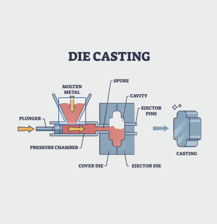
High-Pressure Die Casting (HPDC) forces molten non-ferrous alloy into a reusable tool steel cavity under extreme pressure. Metal freezes within milliseconds under sustained hydraulic force, enabling fast ejection and cycle resets.
For high-volume consumer, industrial, and automotive assemblies, die casting parts offer high consistency across production runs reaching hundreds of thousands of cycles.
Advantages of Die Casting Components
-
Rapid Production Cadence: Hot-chamber machines run up to 15 shots per minute for zinc, while cold-chamber aluminum presses cycle every 30 to 60 seconds, producing thousands of die casting components per shift.
-
Intricate Thin-Wall Capabilities: High injection pressures push metal into wall thicknesses as thin as 0.8 mm, lowering component weight without sacrificing structural rigidity.
-
Low Per-Part Processing Labor: Parts exit the tool near-net-shape, needing only trimming presses, shot-blasting, or brief vibratory tumbling before packaging.
Inherent Drawbacks of Die Casted Parts
-
Trapped Core Porosity: Turbulent molten flow traps mold release agents, vapor, and air. While rapid chilling forms a dense 0.5–1.0 mm exterior skin, the core retains 3% to 5% void volume.
-
Secondary CNC Machining Risks: When precision CNC lathes or mills cut deeper than 1.0 mm to create O-ring seats, BSPP/NPT pipe threads, or internal bores, the porous core is exposed. Under hydraulic or gas pressure testing, these voids link up into leakage paths, causing rejection unless expensive secondary vacuum resin impregnation is applied.
-
Inability to Withstand High-Temperature Heat Treatment: Conventional die cast parts cannot undergo T6 solution treating; internal micro-voids expand under elevated temperatures (> 350°C), blistering the exterior.
3. Silica Sol Investment Casting: The Premier Method for Stainless Steel
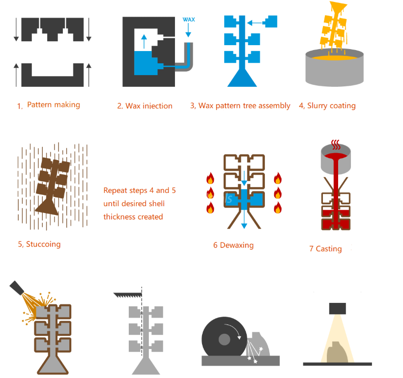
Silica sol investment casting represents the high-precision tier of the lost-wax method. It uses an aqueous colloidal silica emulsion (nanometer-scale SiO2 particles in liquid) as the primary refractory binder to build a multi-layered ceramic shell around disposable wax patterns.
Unlike coarse water-glass processes, silica sol creates an inert, dense ceramic shell capable of withstanding molten alloys above 1600°C without core breakdown or metal penetration.
Material Compatibility and Pressure Tightness
-
High-Melting-Point Metal Compatibility: Readily pours 304, 316, 316L, duplex stainless steels, tool steels, and nickel superalloys—materials that destroy permanent steel molds.
-
Hermetic Pressure Tightness: Laminar gravity fill allows gases to vent through the porous ceramic shell. After heavy CNC turning, drilling, and thread tapping, the component remains dense, preventing pressure-boundary weeping.
-
Intricate Internal Geometries: Water-soluble or multi-piece wax cores create complex interior flow channels and reverse undercuts impossible with rigid metal tools.
The Reality of Tooling and 30 to 45-Day Production Lead Times
A common misconception among buyers is that investment casting tooling is trivial in cost and timeline. For industrial stainless steel investment casting, wax injection dies are complex pieces of equipment:
-
Tooling Investment & 30-Day Lead Time: Producing precision stainless components with internal undercuts, thread cores, or pull-apart features requires CNC-machined aviation-grade aluminum or P20/NAK80 pre-hardened steel dies with mechanical sliders. Fabricating, testing, and debugging these dies takes 30 days before T1 wax samples are qualified.
-
Batch Production Takes 30 to 45 Days: The physical nature of the silica sol shell build cannot be rushed. Building 5 to 7 ceramic layers demands 12 to 24 hours of ambient drying per coat under controlled humidity and temperature. Combined with autoclave dewaxing, 1100°C kiln firing, vacuum or gravity pouring, shakeout, gate cutoff, and acid pickling, a batch run requires 30 to 45 days.
4. Metallurgical Comparison: Die Casting Alloys vs. Investment Cast Steels
Alloy Feasibility and Melting Points
Commercial die casting is limited to aluminum, zinc, magnesium, and specialized copper alloys. High-melting-point materials like austenitic stainless steel (melting point > 1400°C) cannot be die-cast in commercial production; liquid stainless steel causes severe thermal shock, soldering, and cracking on tool steels like H13 within dozens of shots.
If your bill of materials specifies 304, 316L, or alloy steel, silica sol casting is the correct metallurgical route.
Thermal Treatment and Structural Integrity
Standard non-ferrous die castings blister when subjected to solution heat treatment because internal gases expand under high temperatures. Conversely, investment cast steel components can be fully normalized, quenched, tempered, or solution-annealed to achieve peak tensile strength, hardness, and corrosion resistance.
5. Engineering Selection: Process Decision Framework
Choose High-Pressure Die Casting When:
-
The material is strictly aluminum, zinc, or magnesium.
-
Annual order volume is high (tens to hundreds of thousands of parts) to amortize the substantial upfront tooling investment.
-
The profile includes thin cross-sections (down to 0.8 mm) across broad surface areas.
-
Machining is limited to light skin passes that do not breach the outer chill layer.
-
Fast production cycle times (seconds per piece) are mandatory once tooling is validated.
Choose Silica Sol Investment Casting When:
-
The material must be corrosion-resistant stainless steel (304, 316L), duplex steel, or carbon steel.
-
The component holds pressurized media (hydraulic fittings, valve bodies, fluid connectors) and undergoes deep CNC turning or threading.
-
Internal channels, undercuts, or complex draft-free geometry cannot be pulled with rigid metal mold cores.
-
The project schedule accommodates a 30-day precision wax tooling window and a 30- to 45-day shell production cycle.
6. Frequently Asked Questions (FAQ)
Can stainless steel be formed using high-pressure die casting?
No. High-pressure die casting cannot commercially process stainless steel. The extreme melting point of stainless steel (> 1400°C) causes rapid thermal erosion, soldering, and mechanical breakdown of hardened tool steel dies within very few cycles. Precision stainless components require silica sol investment casting, hot forging, or metal powder injection molding (MIM).
Why does silica sol casting take 30 to 45 days for batch manufacturing?
Unlike water-glass casting, which relies on fast chemical hardening agents, silica sol binders cure via physical moisture evaporation under strict temperature and humidity control. Applying 5 to 7 layers of refractory zircon slurry and sands takes 4 to 7 full days of wind drying. Factoring in wax injection, assembly tree building, dewaxing, 1100°C shell firing, pouring, shell knockout, gate grinding, heat treatment, and dimensional correction, the standard batch production cycle requires 30 to 45 days.
Why do machined die cast parts leak under pressure testing?
Die casting relies on high-velocity liquid injection, which traps turbulent air, gas, and volatilized mold lubricants inside the cavity. While the surface forms a dense chill skin, the core remains porous (3%–5% gas and shrinkage voids). When CNC tooling cuts through that skin to form threads or O-ring grooves, it exposes interconnected internal voids, creating leak paths for pressurized fluids or gases.
Ready to Optimize Your Component Sourcing?
Balancing tooling budgets, lead times, and post-machining sealing performance requires precise process matching from the design stage. If your project involves tight-tolerance fluid connections, valve bodies, or precision CNC-machined components, partner with an engineering team that understands both raw blank integrity and secondary machining tolerances.
Contact our engineering team today:
-
Upload your 3D CAD files (STEP, IGS, or PDF drawings) for a complete manufacturing feasibility review.
-
Receive an actionable DFM (Design for Manufacturability) analysis and comprehensive tooling quotation within 24 hours.