In mechanical linkages, drive mechanisms, lead screw adjusters, and fluid valve controls, a cross pin and shaft connection is one of the most widely used methods for transferring torque and locking axial positions. At first glance, the assembly appears deceptively simple: drill a radial through-hole across a turned metal shaft and press in a standard metal pin.
However, mechanical engineers and overseas procurement teams frequently encounter costly field failures after mass production: cross pins loosening, shifting, or falling out entirely under operational vibration or long-distance ocean shipping.
Simply relying on a standard smooth dowel pin and a straight press fit is often insufficient for dynamic applications. Below is an engineering breakdown of why smooth pins walk out of cross-drilled shafts, how knurled pin teeth improve retention, and why hole staking (swaging) provides the ultimate mechanical interlock against vibration.
1. Why Standard Smooth Pins Fall Out of Cross-Drilled Shafts
Standard cylindrical dowel pins rely entirely on an interference fit (such as ISO H7/m6 or H7/p6) between the pin outside diameter and the reamed cross-hole in the shaft.
While this works in static, shock-free environments, it introduces critical vulnerabilities in real-world operating conditions:
-
Machining Tolerance Stack-up: Holding hole diameter tolerances within ±0.01 mm across tens of thousands of turned parts is challenging. If a cross-hole is drilled slightly oversize or the pin diameter runs on the low limit of its tolerance band, the press-fit insertion force drops sharply.
-
Fretting Wear Under Cyclic Load: Alternating rotational torque and continuous high-frequency vibration induce microscopic relative slip between the contact surfaces. Over time, this fretting action wears away the micro-peaks of the metal, eroding interference until the joint develops a clearance gap.
-
Thermal Expansion Mismatch: When assemblies cycle through operating temperature swings, differences in thermal expansion between components can relax radial compressive grip, allowing gravity and centrifugal forces to push the pin out.
2. Stage 1 Optimization: Upgrading to Straight Knurled Pins
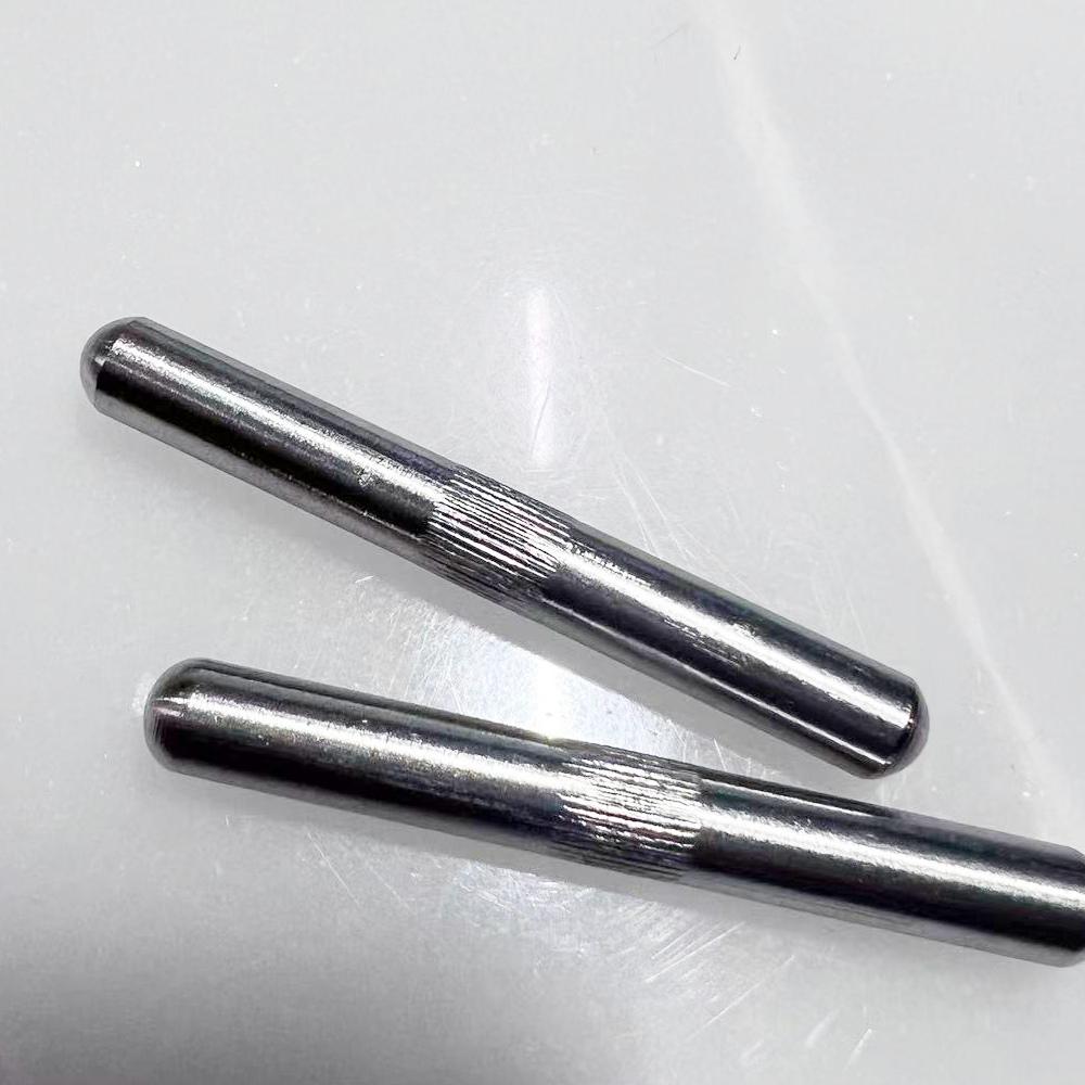
To eliminate reliance on sub-micron press-fit tolerances, the first proven design improvement is switching from smooth pins to straight knurled pins (longitudinally serrated pins).
[Smooth Chamfered End] ===== [Straight Knurled Teeth] ===== [Smooth Chamfered End]
      (Lead-in Guide)            (Interference Zone)             (Lead-in Guide)
-
Micro-Broaching Action: The outside diameter across the knurled crests is intentionally manufactured larger than the shaft hole. As the pin is pressed in, the hardened vertical teeth cut into the softer bore wall, broaching miniature mating keyways directly into the shaft.
-
Elevated Push-Out Force: Straight knurling increases frictional surface contact area and mechanical engagement, raising push-out and retention resistance by 200% to 300% compared to a bare smooth pin.
-
Lead-in Pilot Chamfers: Both ends of the pin retain smooth, unknurled diameters with generous radii or 15° to 30° chamfers. This ensures automated bowl feeders or robotic assembly grippers can align and lead the pin cleanly into the shaft hole without shaving bore edges prematurely.
3. Engineering Trade-Off: Fine Pitch vs. Coarse Pitch Knurling
When specifying knurled pins for a cross-drilled shaft, tooth pitch and depth must be matched to your base material and performance requirements:
Fine Pitch Knurling
-
Characteristics: Shallower tooth depth and tighter tooth spacing (pitch ≤ 0.5 mm).
-
Engineering Limitation: Fine teeth have a lower tooth height. If the shaft cross-hole has a slight positive tolerance variation, fine teeth cannot achieve sufficient radial bite depth. Under high shock loads, the shallow serrations can shear smooth, allowing the pin to walk out.
Coarse Pitch Knurling
-
Characteristics: Deeper tooth valleys and wider tooth spacing (pitch ≥ 0.8 mm).
-
Engineering Limitation: While coarse teeth provide massive push-out resistance, the displaced metal volume is significant. Pressing coarse teeth into a precision shaft requires high insertion force, which can distort the shaft’s outside diameter. Furthermore, displaced metal can push outward, forming raised burrs and extruded metal flash around the hole exit that require costly secondary deburring.
The Engineering Balance
For most carbon steel, stainless steel, and brass shafts, a balanced medium knurl pitch between 0.5 mm and 0.8 mm provides optimal bite depth (maintaining retention push-out forces between 500 N and 1,500 N) without ovalizing the shaft or generating exit-hole burrs.
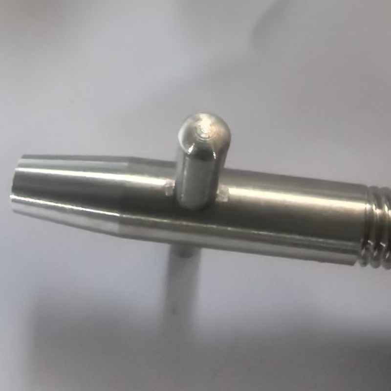
4. The Ultimate Zero-Dropout Fix: Automated Hole-Edge Staking
A real-world engineering case from our manufacturing line illustrates why even knurled pins require secondary containment for demanding shipments:
The Overseas Logistics Case:A batch of turned cross pin and shaft assemblies was manufactured with precision-knurled pins and passed 100% factory push-out force tests. However, after 30+ days of ocean container transit and long-haul trucking to an overseas client in the United States, several assemblies arrived with the cross pins displaced. Continuous sea container vibration, combined with broad temperature cycles, had vibrated the knurled pins past their friction threshold.
       [ Staking Punch Tool ]
              ▼   ▼
       ┌───┐         ┌───┐  <- Shaft Body
       │   │\       /│   │  <- Deformed Metal Rim (Staked Lip)
═══════╪═══╪═════════╪═══╪═══════  <- Retained Knurled Pin
       │   │/       \│   │  <- Deformed Metal Rim (Staked Lip)
       └───┘         └───┘  <- Shaft Body
The Solution: Post-Assembly Staking (Swaging)
To permanently eliminate dropout risks, we implemented a dedicated mechanical staking operation immediately following pin insertion:
-
Controlled Local Deformation: After the knurled pin is pressed to center, automated hydraulic or pneumatic staking punches strike the shaft face immediately adjacent to both ends of the cross-hole (typically 0.3 mm to 0.5 mm from the edge).
-
Metal Displacement Lip: The localized impact forces the shaft base metal to plastically flow inward, creating a permanent mechanical retaining rim (staked collar) over the perimeter of the pin hole.
-
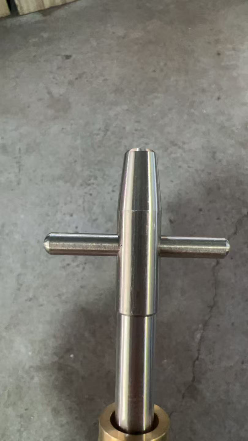
100% Physical Mechanical Interlock: The knurled teeth resist rotation and micro-axial shift, while the staked outer rim acts as a solid metal barrier. Even under extreme dynamic vibration, continuous shock reversals, or rough ocean freight, the pin cannot escape the cross-hole.
5. Performance Matrix: Pin Retention Methods in Shaft Assemblies
| Assembly Method | Key Manufacturing Steps | Vibration Resistance | Dimensional Precision | Production Best Fit |
| Smooth Pin + Standard Hole | Ream hole + press-fit smooth pin | Low (Vibration causes pin walkout) | Relies on tight sub-micron hole/pin tolerances (±0.005 mm) | Non-critical, static indoor fixtures with zero vibration |
| Fine Knurled Pin | Drill/ream hole + press fine-pitch pin | Moderate (2x push-out force of smooth pins) | High precision; zero metal displacement or surface burrs | Light-duty hand controls and low-torque mechanisms |
| Coarse Knurled Pin | Drill hole + high-tonnage press coarse pin | High (Deep tooth bite into hole wall) | Lower precision; risk of hole-rim burrs and shaft ovality | Heavy-duty structural parts where cosmetics and burrs are non-critical |
| Optimized Knurled Pin + Staking | Drill hole + press balanced knurl pin + precision staking | Maximum (100% positive physical mechanical interlock) | High precision; clean appearance without secondary deburring | Export assemblies, automotive linkages, and high-vibration equipment |
6. Frequently Asked Questions (FAQ)
Can a staked cross pin and shaft assembly be disassembled for maintenance?
Staking creates a semi-permanent to permanent mechanical interlock. While a pin can be pressed out using a high-tonnage hydraulic repair arbor, doing so shears the staked metal retaining lip and damages the knurled teeth. For assemblies requiring frequent field disassembly, a threaded taper pin, cross bolt with locknut, or spring coil roll pin is preferable. For lifetime maintenance-free components, staking provides the highest reliability at the lowest unit cost.
Will the staking force bend the shaft or alter critical journal diameters?
No. High-precision staking relies on custom-contoured lower nesting fixtures that support the full circumference of the shaft directly beneath the cross-hole. The staking punch acts strictly on localized chamfer zones (within 0.3 mm to 0.5 mm of the hole rim) with precisely metered stroke depth and tonnage, leaving shaft straightness, roundness, and surface finishes intact.
How do you verify cross pin retention during production quality checks?
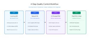
Quality verification includes three standard steps:
-
First-piece destructive push-out force testing using a calibrated digital load-cell press to verify peak retention tonnage against drawing specs.
-
100% optical or depth-micrometer inspection of the staked indentation geometry to confirm full, symmetrical metal flow around both hole rims.
-
High-frequency pneumatic shake testing on lot samples to verify zero axial movement under prolonged simulated transport vibration.
Optimize Your Precision Pin and Turned Shaft Assemblies
Experiencing pin looseness in the field, managing high assembly scrap rates, or seeking an OEM manufacturing partner who engineers true mechanical reliability into every cross pin and shaft?
-
Send your 2D manufacturing drawings (PDF/DWG) and 3D CAD files (STEP/IGES) directly to our engineering team.
-
Receive an actionable Design for Manufacturability (DFM) assessment covering knurl geometry, staking feasibility, and factory-direct volume pricing within 24 hours.
-
Every shipment includes material test reports (MTR), heat treatment certification, push-out retention test data, and export-grade protective packaging.