A frequent question from mechanical engineers and procurement specialists is straightforward: Can stainless steel be polished to a mirror finish?
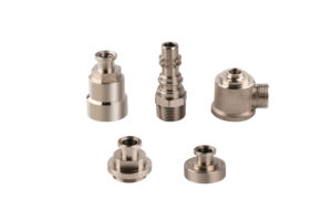
Yes, stainless steel can be polished to an exceptional mirror finish (#8 finish, Ra ≤ 0.1 μm). In precision manufacturing, polishing is routinely specified for precision CNC machinery parts, valve components, and critical fluid hardware like 304 stainless steel fittings and marine-grade 316 stainless steel fittings.
However, in a professional CNC machine shop, mirror polishing is fundamentally a micro-subtractive cutting process, not just cosmetic buffing. Achieving a flawless reflective surface without compromising drawing tolerances requires strict control over raw material blanks, pre-machining surface roughness, wheel hierarchies, and geometry constraints.
1. Raw Blank Forming: How the Starting Material Dictates Polishing Feasibility
The initial blank forming method determines internal metal density, grain structure, and porosity, setting the physical upper limit for surface finish quality.
CNC Machinery Parts from Solid Bar Stock
-
Precision CNC machinery parts turned from solid, cold-drawn bar stock offer the highest density and structural uniformity.
-
With no internal shrinkage or porosity, solid bar components in grades like 304 or 316L provide the most consistent base for high-spec mirror finishes with minimal scrap risk.
Cold Heading Parts (Cold Formed Blanks)
-
High Density Advantage: Cold heading uses high-tonnage multi-station presses to plastically deform wire into near-net blanks. The internal grain structure is thoroughly compressed, eliminating casting porosity and preventing abrasive wax from clogging micro-voids.
-
Work-Hardening Pitfall: Austenitic stainless steel work-hardens rapidly. On cold heading parts, regions subjected to extreme plastic deformation (such as expanded collars, hex flats, or flanges) can surge in hardness from HRB 80 to over HRC 35, while the core remains softer.
-
Shop-Floor Solution: Under a buffing wheel, uneven hardness causes differential material removal, leading to wavy optical reflections and out-of-round features. Cold-headed blanks must undergo a solution annealing treatment (heated to ~1050°C followed by rapid quench) prior to finish CNC turning and mirror buffing to equalize core and surface hardness.
Precision Forging Parts
-
Closed-die hot forging yields continuous grain flow lines and exceptional mechanical strength for high-pressure components.
-
Before buffing, forging scale, decarburized outer layers, and coarse grain boundaries must be completely removed during rough and finish CNC turning. Inadequate heat treatment will trigger an irreparable “orange peel” texture under buffing shear forces.
Sand Castings (Avoid for High-Reflectivity Mirrors)
-
Sand-cast blanks contain micro-shrinkage porosity and subsurface gas pockets.
-
Machining exposes these micro-cavities, and high-speed buffing packs dark polishing compound and swarf permanently into the voids, creating unremovable dark spots.
2. Alloy Selection: The Free-Machining Trap vs. Fitting-Grade Alloys
-
The Grade 303 Pitfall: AISI 303 includes added sulfur (S ≥ 0.15%) to form manganese sulfide (MnS) inclusions for fast CNC chip breaking. During high-speed buffing, these inclusions tear out of the matrix, producing severe micro-pitting and comet-tail streaks. Grade 303 should never be specified for mirror finishes.
-
304 Stainless Steel Fittings & SS 304 Fittings: General-purpose austenitic stainless steel with low sulfur content and excellent ductility. High-grade ss 304 fittings and 304 stainless steel fittings achieve clean, continuous mirror reflections ideal for architectural hardware, beverage handling, and commercial fluid systems.
-
316 Stainless Steel Fittings: Alloyed with 2% to 3% molybdenum, 316 provides superior resistance to chlorides, pitting, and acids. Cleanly melted 316 stainless steel fittings are the benchmark for sanitary pharmaceutical piping, marine hardware, and high-purity chemical connections requiring Ra ≤ 0.2 μm or electropolished finishes.
-
Martensitic Grades (420 / 440C): When hardened and tempered to HRC 50 or higher, these alloys feature an exceptionally dense, rigid matrix. They polish to an ultra-crisp, deep optical mirror finish with sharp corner retention, making them ideal for valve needles and surgical components.
3. Cost-Effective Polishing: The “Ra 0.5–0.8 μm” CNC Rule
A common misconception is that rough CNC turning (Ra 1.6–3.2 μm) can simply be buffed out on a wheel. In production, this approach leads to excessive labor costs, high wheel wear, and scrapped tolerances.
-
Pre-Machining Sets the Cost: Buffing out heavy turning tool marks requires aggressive wheel pressure and extended dwell times. The resulting frictional heat distorts parts and burns off critical dimensions.
-
The Golden Standard: CNC machinists must use specialized wiper inserts and fine feed rates to turn the surface directly down to Ra 0.5 to 0.8 μm (or better) in the lathe.
-
Minimal Stock Removal: When the pre-machined base is already smooth, the buffing sequence only needs to remove 0.003 mm to 0.005 mm of microscopic peaks. Polishing cycle times drop by more than 60%, and critical dimensional tolerances remain fully protected.
4. Does Mechanical Polishing Distort Outer Diameters and Runout?
Yes. Without dedicated fixturing, physical buffing alters outer diameter (OD) geometry and ruins runout.
Buffing wheels are compliant tools that deform under load. Uncontrolled manual polishing introduces severe geometric errors:
-
Out-of-Roundness (Ovality): Uneven hand pressure against the spinning wheel grinds more material from localized spots, turning precision cylindrical ODs into lobes or ovals.
-
Edge Rounding & Chamfer Washout: Polishing wheels catch sharp shoulders and precision sealing chamfers, collapsing functional corners and washing out sealing angles.
-
Runout Degradation: Differential material removal along a shaft or fitting will destroy concentricity. A tight runout of ≤ 0.03 mm held on the CNC lathe can easily blow out to 0.06 mm or more on an unguided buffing wheel.
Process Control: Precision diameters must be mounted on rotating mandrels, dead centers, or motorized steady-rests to ensure uniform peripheral speed and consistent, controlled contact pressure.
5. Multi-Stage Buffing Hierarchy: Wheels and Compounds
Achieving an optical #8 mirror requires a structured, multi-stage progression. Skipping stages results in visible micro-scratches under direct light:
| Polishing Stage | Buffing Wheel Type | Abrasive Compound | Operational Objective |
| Stage 1: Cut Buffing | Sisal Wheel (Coarse, dense natural fiber) | Black Emery or Fast-Cut White | High cutting force; flattens residual CNC turning lines to bring Ra down to ~0.3–0.4 μm. |
| Stage 2: Intermediate Color | Spiral Stitched Cotton Wheel (Firm, stitched cotton plies) | Green Rouge (Chromium Oxide) | Removes sisal spiral marks, cuts fine micro-scratches, and produces a bright base gloss (Ra ~0.2–0.3 μm). |
| Stage 3: Final Mirror Color | Loose Flannel / Soft Cotton Wheel (Ultra-soft, unstitched airflow design) | High-Grade Blue or White Rouge | Zero aggressive cut; utilizes microscopic burnishing to clear hazing and deliver a deep #8 optical reflection (Ra ≤ 0.1 μm). |
6. Geometry Constraints: Stainless Pipe Fittings vs. Irregular Parts
-
Symmetrical Fittings (Rotational Ease): Cylindrical components, threaded adapters, and stainless steel pipe fittings rotate smoothly on expanding mandrels or rotary chucks. The wheel applies balanced, uniform contact pressure across the entire circumference, keeping polishing costs low and quality predictable.
-
Irregular & Non-Symmetrical Parts: Geometries with cross-holes, deep internal recesses, thin ribs, or asymmetrical lugs prevent uniform wheel contact. Protruding corners suffer from severe edge washout, while internal crevices remain unpolished dark zones.
-
Alternative for Complex Geometries: When irregular manifolds, valve blocks, or deep internal channels require high surface cleanliness, mechanical buffing should be replaced by Electropolishing (EP) or Abrasive Flow Machining (AFM). Electropolishing uniformly dissolves microscopic peaks electrochemically without edge collapse or mechanical stress.
Frequently Asked Questions (FAQ)
Can 304 and 316 stainless steel fittings be polished to the same finish level?
Yes. Both alloys can achieve a #8 mirror finish (Ra ≤ 0.1 μm). However, 316 contains 2% to 3% molybdenum, giving polished 316 stainless steel fittings significantly better pit and corrosion resistance in marine and acidic environments.
Do polished stainless steel parts still need chemical passivation?
Yes. High-speed buffing creates localized friction and heat that depletes the native chromium oxide passive film and may embed microscopic trace debris. After thorough ultrasonic degreasing to strip all polishing waxes, parts must undergo chemical passivation (citric or nitric acid) to rebuild a dense, protective passive layer.
How much material allowance should be left for mirror buffing on drawings?
Under controlled shop conditions starting from a fine turned surface (Ra 0.5–0.8 μm), mechanical mirror polishing typically removes 0.003 mm to 0.008 mm per side. This allowance should be incorporated into upper dimensional limits for critical bearing fits or sealing diameters.
Why do cold heading parts sometimes show cloudy patches after polishing?
This is caused by localized work-hardening differences across deformed sections. Without intermediate solution annealing, uneven material hardness leads to inconsistent abrasive cut rates and hazy optical distortion under the wheel.
Precision CNC Machining & High-Spec Surface Finishing
Achieving mirror-like reflectivity while holding tight geometric tolerances requires synchronized manufacturing—from raw material selection and CNC turning down to Ra 0.5 μm, through to custom-fixtured buffing and ultrasonic cleaning.
Whether you require volume production of custom 304 stainless steel fittings, marine-grade 316 stainless steel fittings, precision-formed cold heading parts, or complex CNC machinery parts, our engineering team controls dimensional tolerances within ± 0.01 mm and runout down to ≤ 0.03 mm.
We sign mutual Non-Disclosure Agreements (NDAs) before evaluating proprietary designs. Submit your 2D drawings and 3D CAD files today for a comprehensive DFM review and rapid production quotation.