Precision engineering drawings frequently misuse geometric tolerances, driving up manufacturing costs and inspection bottlenecks without improving component functionality. Among these, concentricity is the most misunderstood callout in modern manufacturing. With the release of ASME Y14.5-2018, concentricity was officially removed from the standard, urging design engineers to transition to position or runout.
Understanding the difference between concentricity, true position, and circular runout is essential for mechanical engineers, CNC machinists, and procurement specialists seeking to balance strict tolerance control with cost-effective production.
What Is the Concentricity Symbol (◎) in GD&T?
The concentricity symbol consists of two concentric circles (◎). It controls the central axis alignment of a cylindrical feature relative to a specified datum axis.
-
Theoretical Definition: Concentricity establishes a cylindrical tolerance zone centered on the datum axis. It dictates that the median points of all diametrically opposed elements across every cross-section must fall within this tolerance cylinder.
-
Key Misconception: Concentricity does not evaluate surface runout, taper, or circularity. A component can exhibit significant surface wobble and still pass concentricity verification, provided its cross-sectional mass centers remain aligned along the datum axis.
Why Did ASME Y14.5-2018 Eliminate Concentricity?
ASME Y14.5-2018 deleted the concentricity symbol (along with symmetry) to resolve chronic quality control and manufacturing issues:
-
Extreme Inspection Complexity: Concentricity cannot be verified using dial test indicators (DTI) or hard functional gauges. Inspecting median points requires continuous coordinate measuring machine (CMM) mapping of thousands of opposed surface points, making in-line quality assurance slow and expensive.
-
Widespread Over-Specification: Outside of ultra-high-speed rotational assemblies such as dynamic balance turbine rotors, mechanical components rarely require median point alignment.
-
Standardized Replacements: True Position and Runout provide superior control over assembly clearance, static fit, and rotational wobble while significantly reducing inspection overhead.
Concentricity vs. True Position vs. Runout
| Feature Dimension | Concentricity (◎) | True Position (⌖) | Circular / Total Runout (↗ / ↗↗) |
| Standard Status | Deleted in ASME Y14.5-2018; Retained in ISO 1101 | Active standard; Recommended for mating features | Active standard; Recommended for rotating components |
| Controlled Feature | Derived median points of cross-sections | Derived median line (axis) of the feature | Cumulative surface variation during rotation |
| Composite Control | Coaxiality of mass center only | Location and orientation relative to datums | Coaxiality, circularity, taper, and surface wobble |
| Material Modifiers | RFS only (no MMC/LMC bonus tolerance) | Supports MMC and LMC bonuses | RFS only (surface feature based) |
| Inspection Tooling | High-density CMM point-cloud mapping | CMM or functional hard receiver gauges | Dial test indicators (DTI) on V-blocks or centers |
| Production Economics | High scrap risk, slow cycle times, high QA cost | Highly cost-effective for medium to high volume | Lowest cost, real-time in-process shop verification |
When to Choose True Position vs. Runout
-
Choose True Position (⌖ with MMC): Apply this callout for bolt patterns, clearance holes, and static shaft-to-bore assemblies. Specifying the Maximum Material Condition (MMC) modifier grants bonus tolerance as feature sizes depart from MMC, enabling rapid quality buy-off using functional go/no-go pin gauges.
-
Choose Runout (↗ Circular / ↗↗ Total): Apply this callout for drive shafts, hydraulic couplings, high-pressure pipe fittings, and bearing journals where dynamic rotational balance and seal integrity are paramount. Runout directly verifies the functional surface against the rotating datum axis.
CNC Machining Best Practices for Tight Concentricity and Runout
Holding concentricity and runout within 0.03 mm requires strict tooling, fixturing, and process controls on the shop floor.
-
Single-Setup Turning (Preferred Route): Complete the datum bore, external locating diameters, and primary sealing faces in one single chucking operation. Eliminating part re-clamping eliminates secondary datum shift at the root.
-
Internal Expanding Mandrels for Secondary Setups: When reversing a part to machine threads or opposite shoulders, avoid standard external multi-jaw chucks that can mar finished diameters or introduce runout. Deploy precision-ground internal expanding collets or mandrels that locate directly on the pre-machined bore.
-
High-Pressure Air Blow Protocol: Fine metal swarf trapped between the part shoulder and the fixture face causes angular tilt and runout errors. Operators must purge both the workpiece and locating surfaces with high-pressure air before seating.
-
Twist-and-Seat Loading Technique: When sliding parts onto expanding tooling or against hard axial stops, apply a simultaneous rotary twisting and axial pressing action. This guarantees full flush contact against the locating shoulder, preventing angular tilt and runout rejects.
Real-World Engineering Case: Holding 0.03 mm Concentricity & Ra 1.6 on Stainless Pipe Fittings
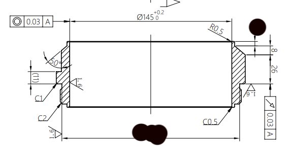
(Note: Specific part numbers and proprietary drawing details are withheld in compliance with our standard Non-Disclosure Agreement.)
Part Specifications & Quality Requirements:
-
Material & Component: 304/316L stainless steel precision pipe fitting
-
Envelope Size: Outer diameter approximately 165 mm, overall length 59 mm
-
GD&T Callouts: Concentricity ≤ 0.03 mm, Circular Runout ≤ 0.03 mm relative to primary datum
-
Surface Finish: Ra ≤ 1.6 μm on external seal diameters and locating bores
The Secondary Setup Challenge:
The internal bore and primary outer diameter were turned in a single setup to maintain true coaxiality. However, the reverse end required single-point threading and shoulder profiling. Standard external three-jaw chucking presented two major quality hazards:
-
Tough stainless steel chips lodged between standard jaws and the finish-turned diameter, scratching the critical Ra 1.6 μm surface.
-
Uneven jaw pressure introduced 0.02 mm to 0.04 mm of axial tilt, exceeding the 0.03 mm runout limit.
The Machining & Tooling Solution:
-
Custom Internal Expanding Mandrel: The engineering team replaced external clamping with a hardened internal expanding mandrel, registering directly against the precision-finished internal bore datum to lock coaxial alignment.
-
High-Pressure Purge Protocol: Before seating each component, an automated high-pressure air blast cleared all locating surfaces to eliminate chip entrapment.
-
Twist-and-Seat Loading: Operators applied a twist-and-seat motion against the ground axial stop, ensuring complete flush face contact and preventing taper or angular wobble.
Final Quality Outcome:
In-process dial indicator verification confirmed that secondary-operation concentricity and circular runout remained consistently between 0.015 mm and 0.020 mm across the entire batch—well within the 0.03 mm tolerance—while keeping the Ra 1.6 μm sealing surfaces 100% scratch-free.
Frequently Asked Questions (FAQ)
Can you measure GD&T concentricity with a dial indicator?
No. A dial indicator riding on a spinning component measures circular runout (a composite check of roundness, eccentricity, and surface variation), not concentricity. Concentricity strictly evaluates cross-sectional median points, which requires high-density CMM point-cloud calculations.
What is the recommended replacement for concentricity on modern drawings?
For rotating components and dynamic sealing faces, replace concentricity with Circular Runout (e.g., Runout within 0.03 mm to Datum A). For static mating parts and clearance fits, replace it with True Position using an MMC modifier.
Why does secondary machining often cause runout and concentricity failures?
Secondary operations often introduce datum transfer errors, uneven jaw chucking pressure, and micro-debris trapped against reference shoulders. Employing precision internal expanding mandrels, clean air blow-offs, and single-setup machining prevents these errors.
Partner with Machining Specialists for Precision Tolerances
Tight GD&T callouts do not have to drive up scrap rates or component unit costs. By optimizing tooling setups and refining drawing callouts for manufacturability, our engineering team holds tolerances down to 0.01 mm on custom stainless fittings, shafts, and precision-turned components.
We sign mutual Non-Disclosure Agreements prior to any drawing review. Upload your CAD models and drawings today for a complimentary DFM analysis and fast turnaround quote.